Image display apparatus

a technology of image display and display screen, which is applied in the direction of static indicating devices, electroluminescent light sources, instruments, etc., can solve the problems of flickering, turning on and off the light emitting period, etc., and achieve the effect of reducing the width of luminance adjustment, reducing flickering of the screen, and adjusting the luminance level

Active Publication Date: 2010-09-21
JOLED INC
View PDF15 Cites 11 Cited by
  • Summary
  • Abstract
  • Description
  • Claims
  • Application Information

AI Technical Summary

Benefits of technology

[0008]On the other hand, an image display apparatus which achieves a high contrast and high picture quality while suppressing the power consumption can be provided if the peak luminance is controlled so as to be low when the average luminance level of the screen display is high but to be high when the average luminance level is low. More preferably, if the peak luminance is controlled for every variation of a field while a screen image is displayed, then the peak luminance can be controlled without proving an uncomfortable feeling to an operator of the screen image and without causing the operator to recognize the variation of the peak luminance. However, as a condition for causing the operator to fail to recognize the variation of the peak luminance, it is necessary that one adjustment step for the variation of the peak luminance by variation of the light emitting period be less than a recognition limit to the luminance variation of the human being. Image display apparatus in the past are configured without paying attention to this point, and this is a subject to be solved.
[0009]Therefore, it is demanded to provide an image display apparatus wherein the peak luminance can be controlled without allowing a variation of the peak luminance to be recognized by an operator and without providing an uncomfortable feeling to the operator.
[0012]Preferably, when the time length of any of the light emitting periods is to be adjusted, the switching transistor sets the difference between different ones of the light emitting periods within one adjustment unit which corresponds to one horizontal period. In this instance, when the time length of one of the light emitting periods is to be increased while the time lengths of the light emitting periods within one field are equal to each other, the switching transistor may preferentially increase the time length of that one of the light emitting periods which is later in time within the field. Or, when the time length of one of the light emitting periods is to be decreased while the time lengths of the light emitting periods within one field are equal to each other, the switching transistor may preferentially decrease the time length of that one of the light emitting periods which is later in time within the field.
[0013]In the image display apparatus, the switching transistor of each of the pixel circuits repeats turning on and off operations by a plural number of times in response to a control signal supplied from the associated scanning line thereby to set the light emitting period, within which the electro-optical element emits light, divisionally to a plural number of light setting periods within one field. Consequently, the luminance level of the screen can be adjusted while flickering of the screen is suppressed effectively. Further, as a characteristic feature of the present invention, the switching transistor of each of the pixel circuits can adjust the plural divisional light emitting periods such that the light lengths thereof are different from each other. Consequently, when compared with an alternative case wherein the time lengths of the divisional light emitting periods are varied collectively, the adjustment width of the luminance level is reduced, and the peak luminance control can be carried out without allowing a variation of the peak luminance to be recognized by an operator and without providing an uncomfortable feeling to the operator. Preferably, the switching transistor adjusts the time length of one of the plural divisional light emitting periods by one adjustment unit (one adjustment step) which corresponds to one horizontal period per one field. By this, the adjustment step for variation of the peak luminance by the variation of the light emitting period can be suppressed to a recognition limit of the luminance variation of a human being.

Problems solved by technology

However, the technique of turning on and off the light emitting period as described above involves a problem of flickering.

Method used


Image

  • Image display apparatus
  • Image display apparatus
  • Image display apparatus

Examples


Embodiment Construction

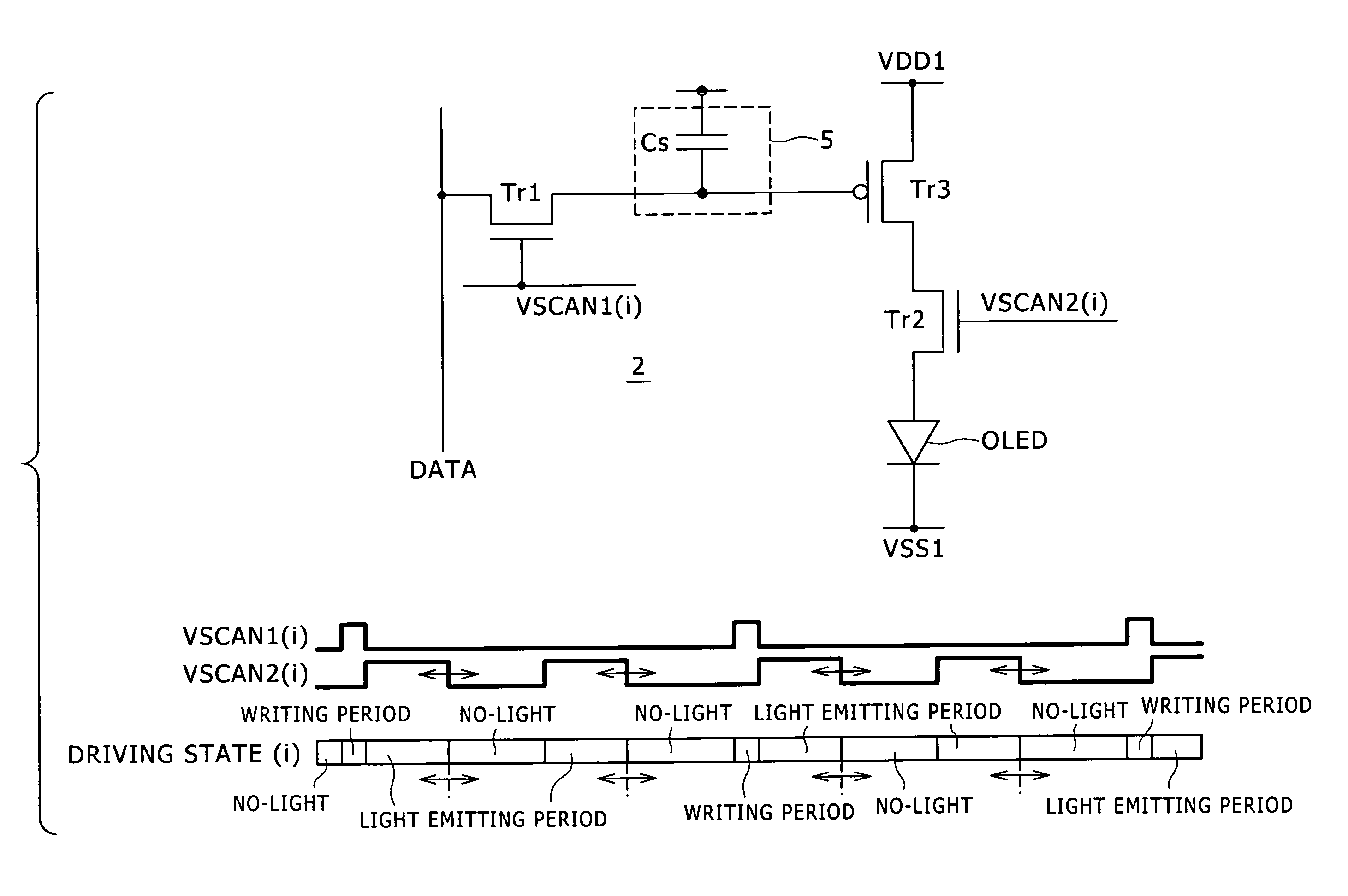
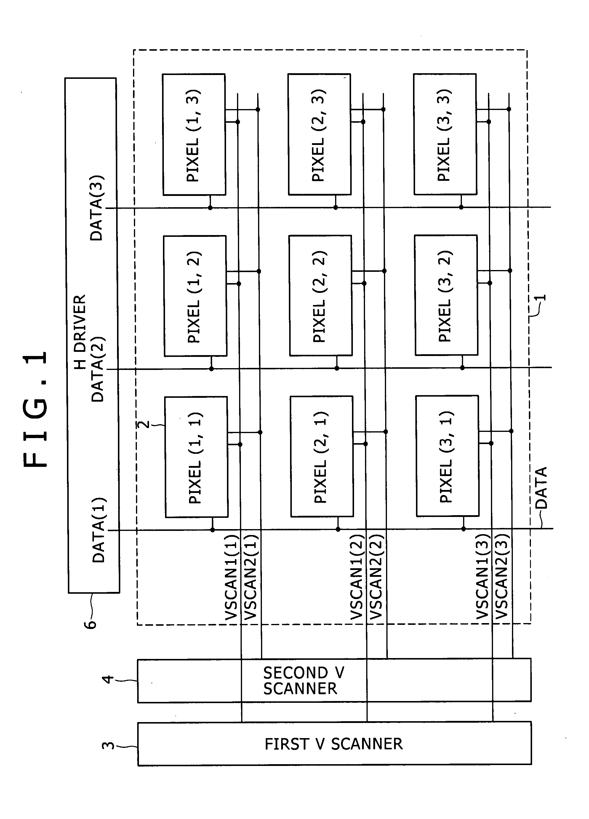
[0023]Referring to FIG. 1, there is shown a general configuration of an image display apparatus to which the present invention can be applied. The image display apparatus shown includes a screen 1. The screen 1 is formed from a set of pixels 2 disposed in rows and columns. Each of the pixels 2 is formed as a pixel circuit whose position is specified by a combination of a row number and a column number placed in parentheses. A V scanner for carrying out line-sequential scanning is disposed on a peripheral side of the screen 1. In the image display shown in FIG. 1, the V scanner is divided into a first V scanner 3 and a second V scanner 4. Meanwhile, an H driver 6 for supplying an image signal is disposed on an upper side of the screen 1.

[0024]In addition to the pixels 2 described above, scanning lines VSCAN and signal lines DATA are formed on the screen 1. The scanning lines VSCAN extend along a direction of a row and successively supply a control signal in synchronism with a horizon...


PUM


Abstract

Disclosed herein is an image display apparatus, including: a plurality of scanning lines extending along rows and configured to successively supply a control signal in synchronism with a horizontal period in order to perform line-sequential scanning over one field; a plurality of signal lines extending along columns and configured to supply an image signal in accordance with the line-sequential scanning; and a plurality of pixel circuits disposed at locations at which the scanning lines and the signal lines intersect with each other and configured to form a screen.

Description

CROSS REFERENCES TO RELATED APPLICATIONS[0001]The present invention contains subject matter related to Japanese Patent Application JP 2006-143328 filed in the Japan Patent Office on May 23, 2006, the entire contents of which being incorporated herein by reference.BACKGROUND OF THE INVENTION[0002]1. Field of the Invention[0003]This invention relates to an image display apparatus and more particularly to an image display apparatus of the active matrix type wherein electro-optical elements such as organic EL (Electro Luminescence) light emitting elements are arrayed in a matrix. The present invention relates more specifically to a screen luminance adjustment technique for a self-luminous image display apparatus.[0004]2. Description of the Related Art[0005]An image display apparatus of the active matrix type wherein a light emitting element such as an organic EL element is used for a pixel is known in the past and disclosed, for example, in Japanese Patent Laid-Open No. 2001-60076. The ...

Claims


Application Information

Patent Timeline
Patent Type & Authority Patents(United States)
IPC IPC(8): G09G3/30H05B44/00
CPCG09G3/325G09G2300/0819G09G2310/0262G09G2320/0247G09G2320/064G09G3/30G09G3/20G09G3/32H05B33/12
Inventor ASANO, MITSURU
Owner JOLED INC
Why Eureka
Try Eureka