Stabplate connections

a technology of stabplates and connections, applied in the direction of sealing/packing, mechanical equipment, borehole/well accessories, etc., can solve the problems of increasing air weight and overall cost, reducing visibility, etc., and achieve the effect of facilitating installation

Inactive Publication Date: 2010-09-28
GE OIL & GAS UK LTD
View PDF18 Cites 11 Cited by
  • Summary
  • Abstract
  • Description
  • Claims
  • Application Information

AI Technical Summary

Benefits of technology

[0023]The invention allows both the use of a vessel of opportunity and, perhaps, less experienced ROV pilots, and will significantly ease installation. The technique is applicable to all hydraulic flying leads but particularly those that contain high collapse resistant (HCR) hoses, as well as steel tube flying leads (SFLs). By judicious design of the lift point and counterweight, the second part of stabplate connection will hang level during lowering regardless of the weight of the flying lead bundle.

Problems solved by technology

However, as umbilicals, for example HFLs, become heavier and more unwieldy this leads to designs with the need for increased buoyancy, which increases in-air weight and overall costs.
With such conventional horizontally connected stabplate connections, the installation vessel is typically decoupled from the installation and involves a remotely operated vehicle (ROV) dragging the umbilical across the seabed, which, in some seabed conditions (e.g. Gulf of Mexico, West Africa) leads to a decrease in visibility due to disturbance of sand or silt.

Method used


Image

  • Stabplate connections
  • Stabplate connections

Examples


Embodiment Construction

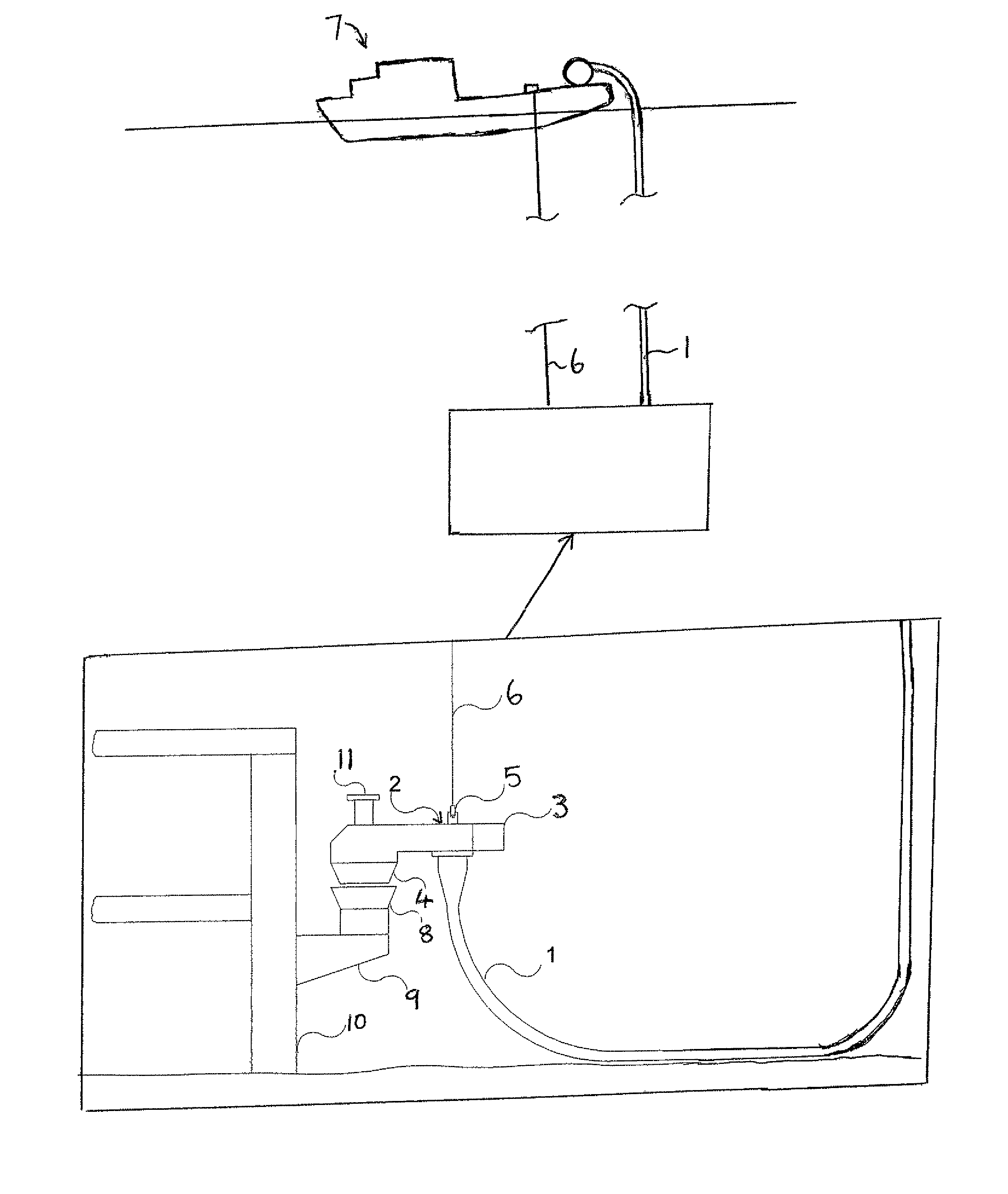
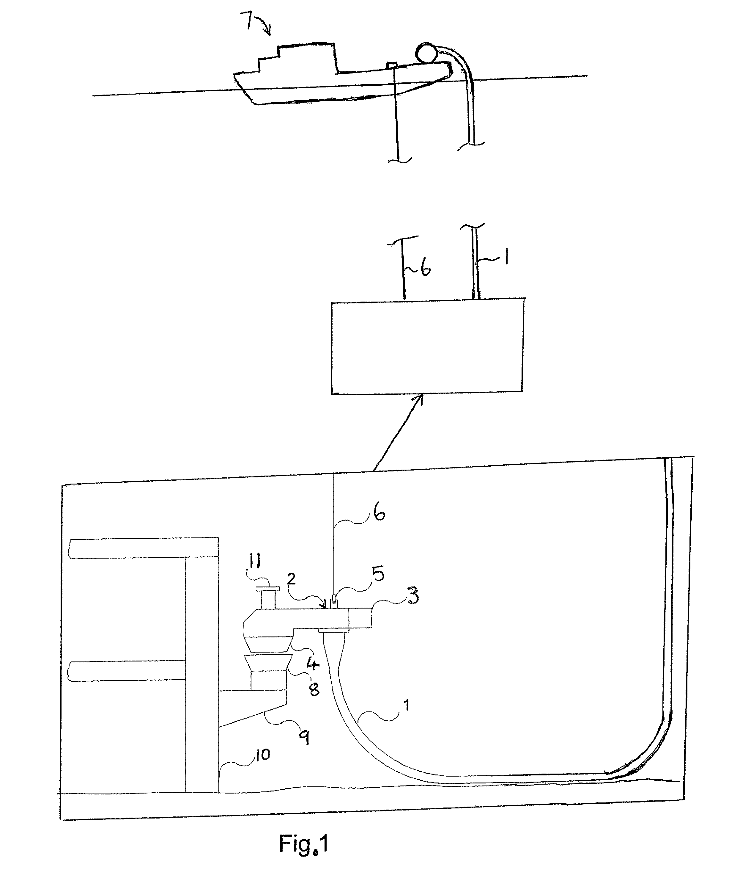
[0025]Referring to FIG. 1, an umbilical 1 is terminated by a connector assembly 2 comprising a first part of a stabplate connection. The umbilical is connected to the underside of assembly 2, between a counterweight portion 3 of the assembly 2 and a wet-mateable connector 4 of the assembly 2. The umbilical 1 could be an umbilical which carries at least one of (for example) electric power, hydraulic power, electrical signals, optical signals and chemicals or an umbilical in the form of an HFL, such as an SFL for example. The assembly 2 is attached by an ROV removable shackle 5 to a lift line 6 from a surface vessel 7, the shackle 5 being attached at a region directly above the region at which the umbilical is attached to the underside of assembly 2. The hydraulic and / or electrical and / or chemical and / or fibre optic feeds in the umbilical 1 are routed within the connector assembly 2 to respective connections in the wet-mateable connector 4, which faces downwards, at the end of the con...


PUM


Abstract

An underwater stabplate connection is provided by lowering a counterbalanced first part of the connection in a horizontal disposition by a lift line, the first part being attached to an umbilical. The first part of the connection mates with a second part of the connection, the second part being attached to an underwater structure such as a well tree.

Description

FIELD OF THE INVENTION[0001]The present invention relates to stabplate connections.BACKGROUND[0002]Subsea structures (such as well trees, subsea manifolds and subsea distribution units) in subsea hydrocarbon extraction or injection wells are supplied with at least one of (for example) electric power, hydraulic power, electrical signals, optical signals and chemicals from a control platform or surface vessel via an umbilical, which could be in the form of a hydraulic flying lead (HFL) such as a steel tube flying lead (SFL). The umbilical is typically terminated with a connector which mates with another connector mounted on a stabplate attached to the subsea structure, such as a tree. Stabplate connections are, historically, made up in a horizontal orientation. However, as umbilicals, for example HFLs, become heavier and more unwieldy this leads to designs with the need for increased buoyancy, which increases in-air weight and overall costs.[0003]With such conventional horizontally co...

Claims


Application Information

Patent Timeline
Patent Type & Authority Patents(United States)
IPC IPC(8): E21B43/01
CPCF16L1/26E21B43/0135E21B33/038E21B17/015
Inventor BARRATT, RICHARD K. O.
Owner GE OIL & GAS UK LTD
Why Eureka
Try Eureka