
Setting an operating bias current for a magnetoresistive head using ratio of target voltage and measured voltage

a technology of operating bias current and magnetoresistive head, which is applied in the field of magnetoresistive head, can solve the problems of increasing signal-to-noise, increasing the quality of read signal, and setting the bias too high, and reducing the lifetime of the mr elemen

Active Publication Date: 2010-09-28
WESTERN DIGITAL TECH INC
View PDF35 Cites 163 Cited by
  • Summary
  • Abstract
  • Description
  • Claims
  • Application Information

AI Technical Summary

Problems solved by technology

Increasing the bias of the MR element typically increases the quality of the read signal (increases signal-to-noise); however, setting the bias too high reduces the lifetime of the MR element.
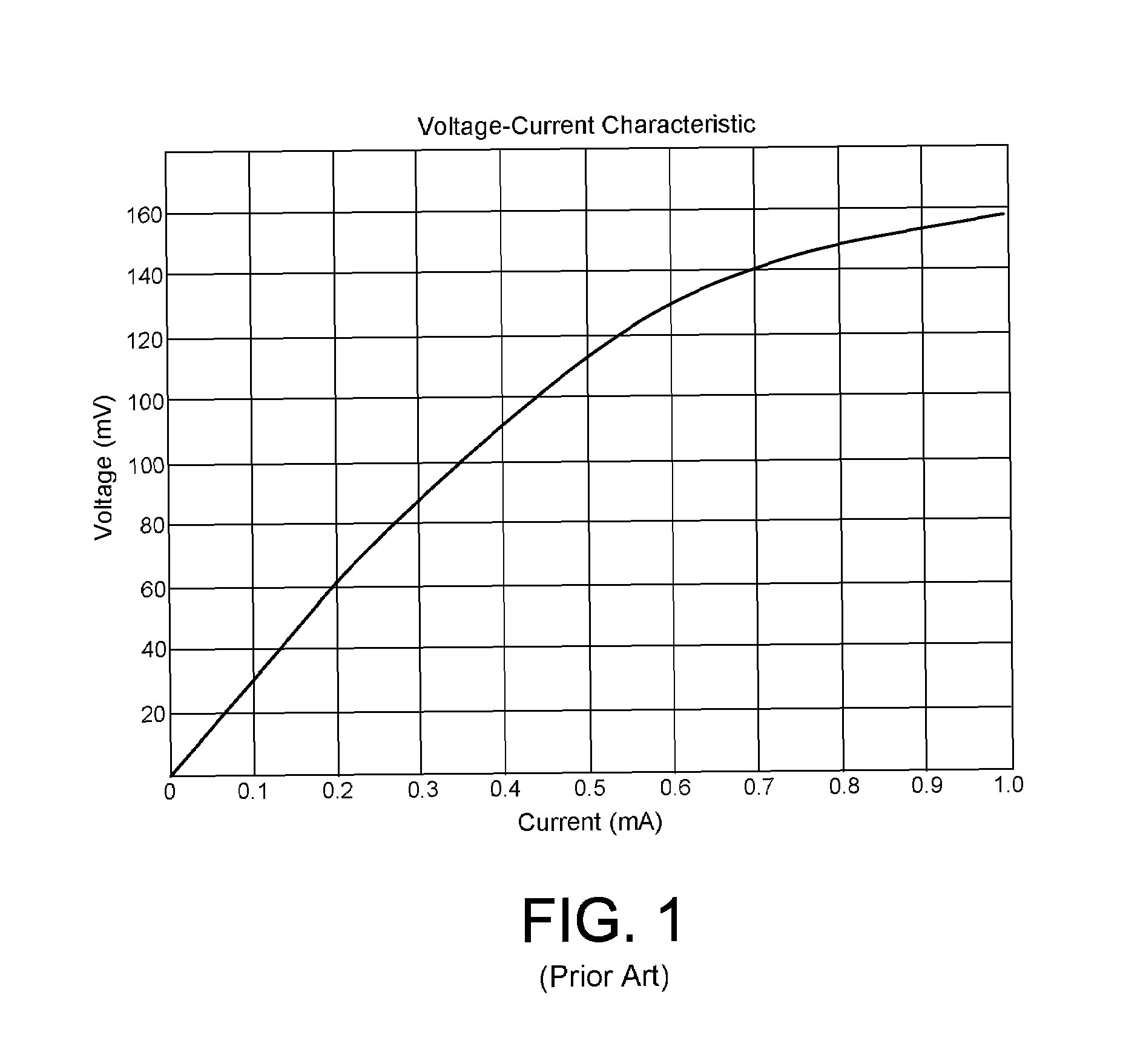
Consequently, the error in estimating the resistance according to a linear transfer function (e.g., using two point extrapolation) induces error in computing the optimal operating bias current.
If the storage device employing the MR element operates with a limited bandwidth, the speed of the algorithm for re-estimating the resistance may impact performance.

Method used


Image

  • Setting an operating bias current for a magnetoresistive head using ratio of target voltage and measured voltage
  • Setting an operating bias current for a magnetoresistive head using ratio of target voltage and measured voltage
  • Setting an operating bias current for a magnetoresistive head using ratio of target voltage and measured voltage

Examples


Embodiment Construction

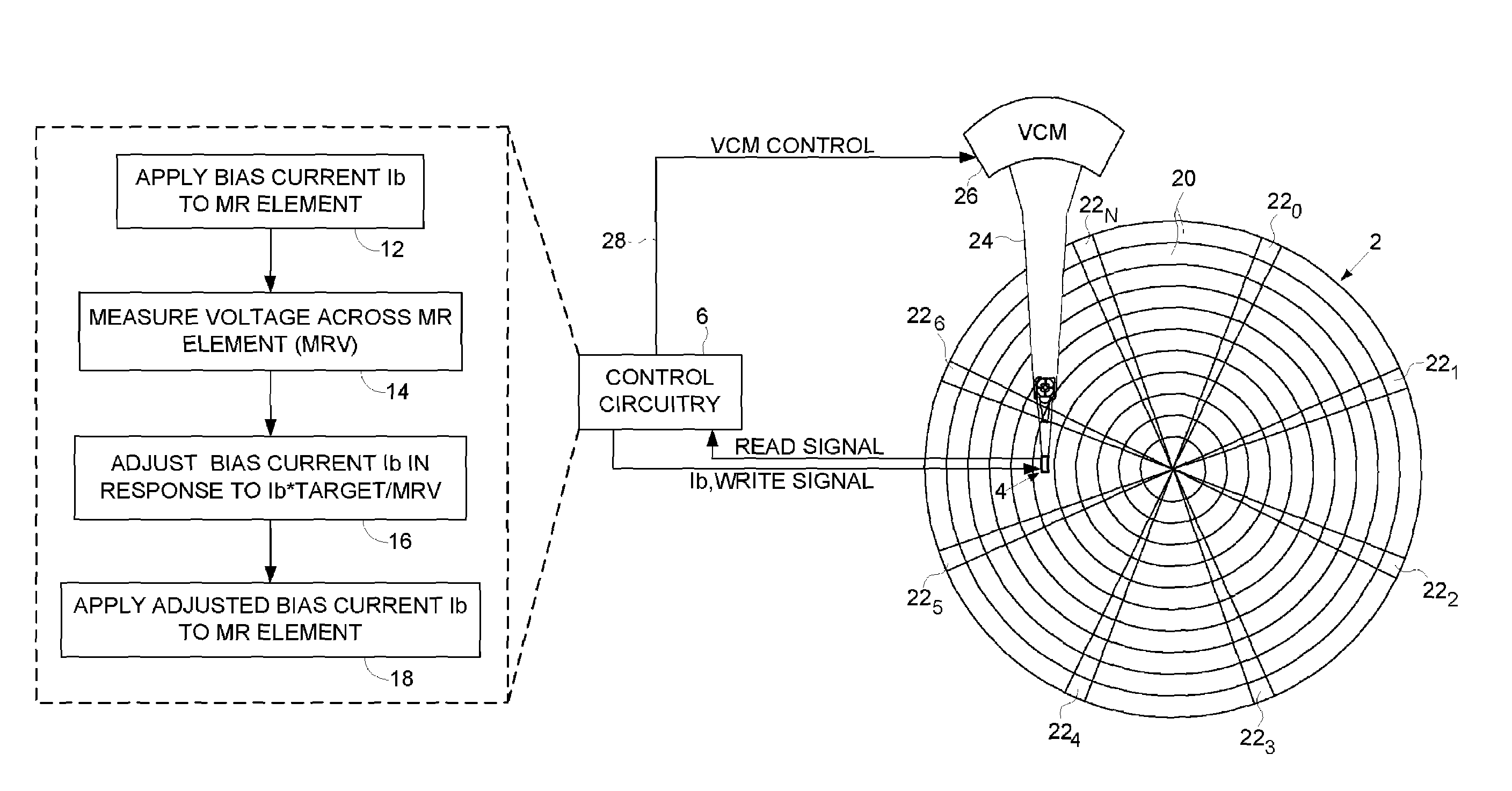
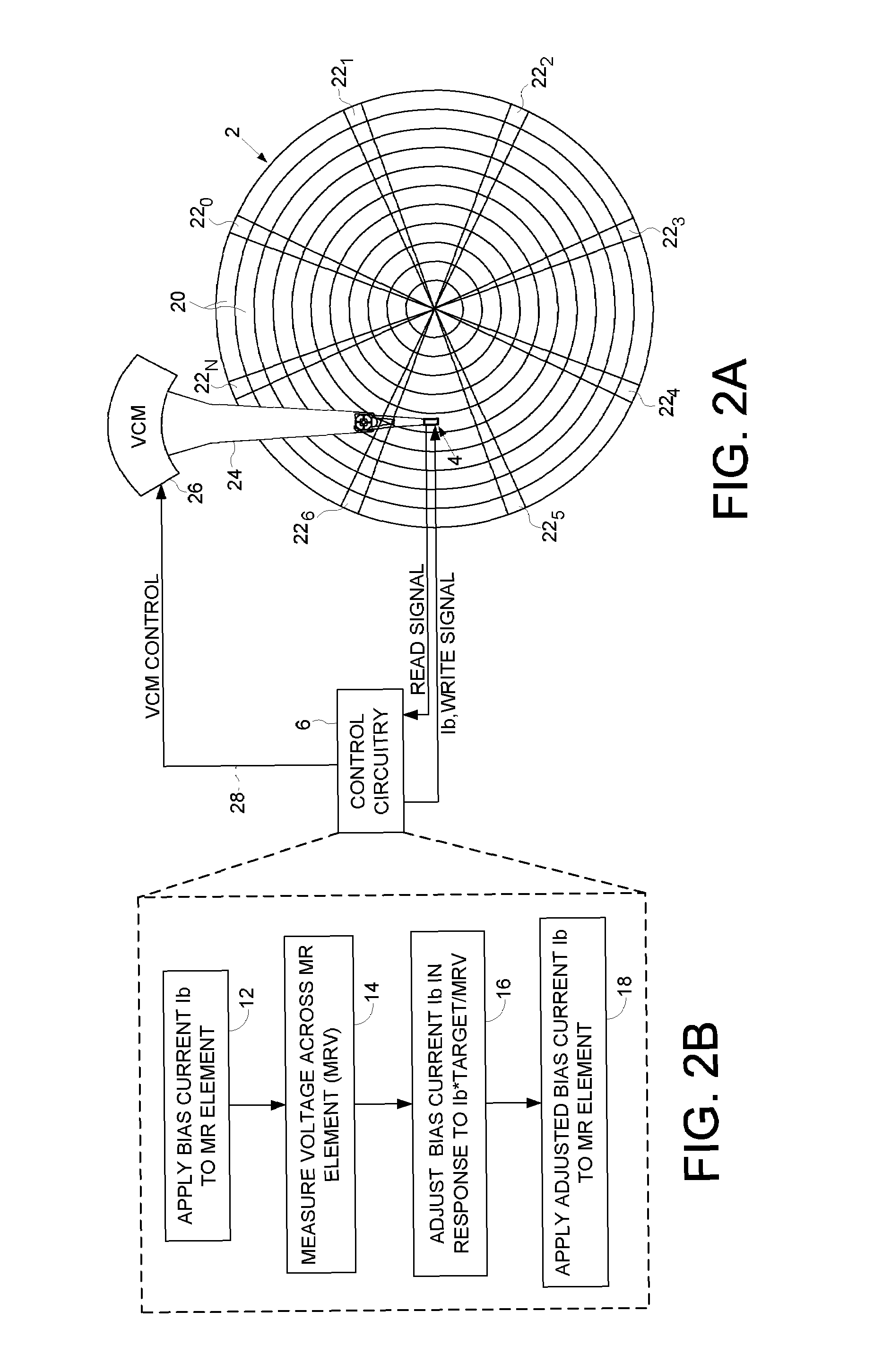
[0009]An embodiment of the present invention comprises a method of setting an operating bias current for a magnetoresistive (MR) element. A bias current is applied to the MR element, and a voltage across the MR element is measured corresponding to the bias current. The bias current is then adjusted in response to the bias current multiplied by a ratio of a target voltage and the measured voltage. The adjusted bias current is then applied to the MR element.

[0010]In one embodiment, the bias current is selected as the target voltage divided by a typical maximum resistance value for the MR element. In another embodiment, the bias current is selected as the target voltage divided by a resistance estimate for the MR element.

[0011]In another embodiment, adjusting the bias current comprises multiplying the bias current by the target voltage divided by the measured voltage.

[0012]In yet another embodiment, the method further comprises measuring the voltage across the MR element corresponding ...


PUM

PropertyMeasurementUnit
voltage Vminaaaaaaaaaa
voltageaaaaaaaaaa

Abstract

A method is disclosed for setting an operating bias current for a magnetoresistive (MR) element. A bias current is applied to the MR element, and a voltage across the MR element is measured corresponding to the bias current. The bias current is then adjusted in response to the bias current multiplied by a ratio of a target voltage and the measured voltage. The adjusted bias current is then applied to the MR element. In one embodiment, the bias current is adjusted until the measured voltage substantially equals the target voltage.

Description

RELATED APPLICATIONS[0001]This application is related to co-pending U.S. patent application titled “SETTING AN OPERATING BIAS CURRENT FOR A MAGNETORESISTIVE HEAD BY COMPUTING A TARGET OPERATING VOLTAGE”, Ser. No. 11 / 761,266, filed on the same day as the present application and incorporated herein by reference.BACKGROUND[0002]1. Field[0003]The present invention relates to magnetoresistive heads. In particular, the present invention relates to setting an operating bias current for a magnetoresistive head.[0004]2. Description of the Related Art[0005]Magnetoresistive (MR) heads are typically employed in data storage devices, such as magnetic tape drives and disk drives, for transducing the magnetic transitions recorded on a magnetic medium into a read signal that is demodulated by a read channel. A MR head comprises an MR element having a resistance that varies in response to the magnetic field emanating from the recording medium. The read signal may be generated by applying a constant ...

Claims


Application Information

Patent Timeline
Patent Type & Authority Patents(United States)
IPC IPC(8): G11B5/03
CPCG11B5/3903G11B2005/0016
Inventor HOGG, DENNIS W.GOODE, JONAS A.TRINH, TUYEN V.
Owner WESTERN DIGITAL TECH INC
Learn More