Method and system for tracking position of an object using imaging and non-imaging surveillance devices

a technology of non-imaging surveillance and tracking position, applied in the field of method and system for tracking the position of an object using imaging and non-imaging surveillance devices, can solve the problems of limiting the capacity of the aviation system, the number of runways, the extent of the navigational and air traffic control (atc) facilities, etc., to facilitate full utilization of existing capacity, facilitate the operation of safe operations, and facilitate the effect of his/her responsibility

Active Publication Date: 2010-09-28
SAAB INC
View PDF17 Cites 23 Cited by
  • Summary
  • Abstract
  • Description
  • Claims
  • Application Information

AI Technical Summary

Benefits of technology

[0033]The method and system described above is particularly suitable for an airport setting, which already has an infrastructure of non-imaging surveillance devices (NSDs) installed for the specific purpose of locating and identifying aircraft and ground vehicles in and around the airport. By employing the method and system of the present invention to supplement that already existing infrastructure, it is possible to remove the requirement that ATC operators have actual line-of-sight contact with the surface environment of the airport. This provides two significant enhancements with respect to traditional ATC infrastructures. First, ATC operators can gain a new visual perspective of the airport without having to relocate or expand the existing ATC tower. Again, since the present invention provides a visual component to the ATC operator through the use of imaging surveillance devices (ISDs), the ATC operator can be positioned at any location, even at a site remote from the airport itself. As a result, the method and system of the present invention overcomes all of the above-discussed problems that will inevitably be encountered by the ATC industry as the amount of air traffic expands in the future.
[0040]It can be appreciated from the foregoing discussion that the method and system of the present invention provide significant advantages over the current ATC infrastructure, and also allow the existing airports to better manage the expected growth of air traffic in the future. There are additional advantages, however, resulting from being able to remove an existing ATC tower or eliminate the need for an ATC tower in new construction. First, the tower removal will provide existing airport facilities with the ability to increase capacity by expanding the existing airport traffic patterns previously constrained by the physical presence of the ATC tower. Second, the removal of the tower also removes a significant airport growth constraint since current flight operations must be routed around the air traffic control tower to ensure safe flight operations.

Problems solved by technology

As it stands now, however, airports today are, in many cases, the limiting factor in aviation system capacity.
These limiting factors include tarmac space, number of runways, number of suitable approaches, and the extent of navigational and Air Traffic Control (ATC) facilities.
Many airports are at or near the capacity limit for their current configuration and thus become bottlenecks for overall aviation system performance and generate significant delay.
While all of these improvements have greatly increased aviation safety in and around airports, the continued growth of air traffic will present new challenges to the industry.
Option (a) suffers from the problem of increased noise pollution in populated areas and the associated complaints from residents.
Due to the limited amount of real estate available around existing airports, especially in metropolitan areas, it will be difficult for existing airports to exercise option (b).
Several airports are building taller multimillion dollar ATC towers for improved airport situational awareness to address this challenge, but as the airport becomes larger and more complex it becomes increasingly difficult to find a single location at which an air traffic control tower can provide the required visibility.
Small airports in turn, will seek solutions to enable growth, but will be hindered by the expenditures required for air traffic services.
One of the most significant expenditures for such small airports will be the cost of a suitable ATC tower.
There are several problems, however, with such traditional ATC towers.
The most obvious problem is the height of the tower itself.
Secondly, since all of the ATC operators reside within the tower, those operators have only a single perspective viewpoint of the entire airport and its surroundings.
This approach is overkill for some operators who are responsible for only a certain segment of the airport (e.g., arrival and departure).
A better position for those operators would be near the ends of the operative runways, but a second ATC tower at such a location would create an unacceptable obstruction for arriving and departing aircraft.
Perhaps the most significant problem with traditional ATC towers has been mentioned above—they are incredibly expensive to erect and maintain.
The current air traffic control model fails to leverage new and emerging technologies to increase safety while reducing costs.
This runs counter to the aviation industry's goal of improving safety while reducing operational costs, year after year.
For the reasons cited above, the traditional approach of tall airport towers at every airport of moderate activity, or the requirement that every airport of moderate activity have some type of air traffic control on-site, is quickly becoming impractical.

Method used


Image

  • Method and system for tracking position of an object using imaging and non-imaging surveillance devices
  • Method and system for tracking position of an object using imaging and non-imaging surveillance devices
  • Method and system for tracking position of an object using imaging and non-imaging surveillance devices

Examples


Embodiment Construction

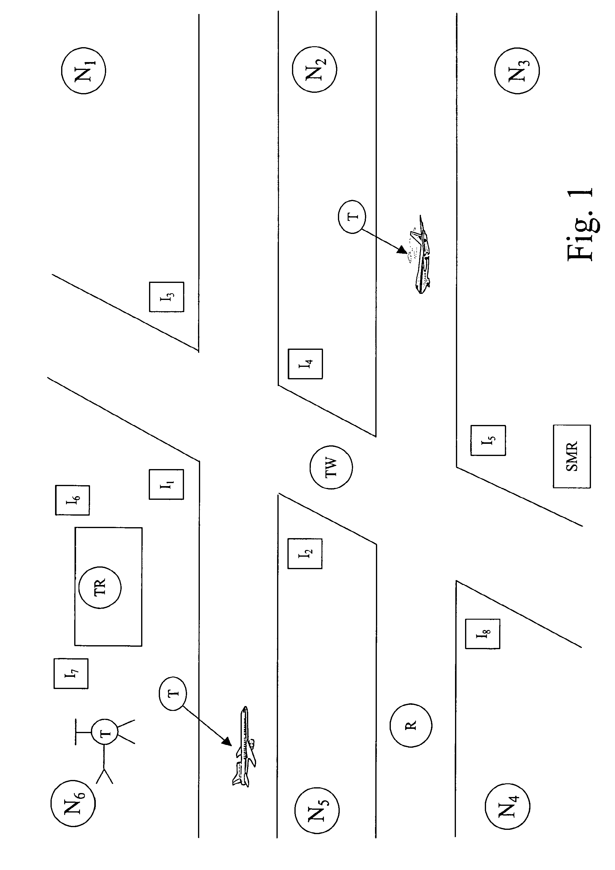
[0049]FIG. 1 is a plan view of a hypothetical airport setting to describe the method and system of the present invention. The airport includes a terminal (TR) located near runways (R) and taxiways (TW) on which aircraft and supporting ground vehicles travel. A plurality (N1-N6) of non-imaging surveillance devices (NSDs) are positioned at known locations around the airport. A plurality (I1-I8) of imaging devices (ISDs) are also positioned at known locations around the airport. FIG. 1 also shows a surface movement radar (SMR) which is used to detect the presence of aircraft and vehicles in and around the airport.

[0050]The NSDs used in the present invention can include any type of terrestrial or space-based surveillance device that does not rely upon imaging to detect the presence of a target. The NSDs can be either “cooperative” surveillance devices, in that they rely upon transmissions emitted from a target itself to detect the presence and position of the target, or “non-cooperative...


PUM


Abstract

A method and system for tracking the position of objects, such as aircraft and ground vehicles around an airport. A transmission from the object is received at a non-imaging surveillance device of known location, the transmission being used to determine the coordinate position of the object within a given time period. Image data for the object is captured by an imaging surveillance device of known location to provide an image of the object within the same given time period. The coordinate position is correlated with the image to provide composite data about the object within the same given time period. The composite data is displayed to a viewer as a visual depiction of the object.

Description

CROSS REFERENCE TO RELATED APPLICATION[0001]This application claims the benefit of U.S. Provisional Application Ser. No. 60 / 643,719 filed Jan. 13, 2005, the entirety of which is incorporated herein by reference.FIELD OF THE INVENTION[0002]The present invention relates to a method and system for tracking the position of an object using imaging and non-imaging surveillance devices. In particular, the present invention relates to a method and system for tracking aircraft and ground vehicles in and around an airport using data supplied by air traffic surveillance devices, such as ADS-B transceivers, and fusing that data with real-time image data of the aircraft and ground vehicles.BACKGROUND OF THE INVENTION[0003]The management of airport terminal operations has always been a daunting task due not only to the aircraft traffic in and around the airport, but also the movement of the associated ground vehicles necessary to service the aircraft. As international commerce has grown over the ...

Claims


Application Information

Patent Timeline
Patent Type & Authority Patents(United States)
IPC IPC(8): G06K9/00
CPCG08G5/0026G08G5/065G01S13/867G01S2013/916
Inventor VIGGIANO, MARC JDONOVAN, TODD AGERRY, MICHAEL JPARKS, LARA MARISA
Owner SAAB INC
Why Eureka
Try Eureka