Method of examining dynamic cardiac electromagnetic activity and detection of cardiac functions using results thereof

a dynamic cardiac electromagnetic activity and detection method technology, applied in the field of dynamic cardiac electromagnetic activity and detection of cardiac functions, can solve the problems of creating interference between signals, imposing discomfort on patients, uncomfortable and potentially dangerous participants, etc., and achieves enhanced differentiation between normal functioning and abnormally functioning hearts.

Inactive Publication Date: 2010-09-28
HORNG HERNG ER +3
View PDF3 Cites 4 Cited by
  • Summary
  • Abstract
  • Description
  • Claims
  • Application Information

AI Technical Summary

Benefits of technology

[0010]In view of the foregoing, the present invention provides a method of examining cardiac electromagnetic activity, wherein differentiation between a normally functioning and an abnormally functioning heart is enhanced.
[0011]The present invention also provides a method of examining cardiac electromagnetic activity, wherein localization of an injured myocardium can be achieved.

Problems solved by technology

Further, in order to obtain two-dimensional signals via ECG, many electrodes need to be placed on the body, which can be impractical and may create interference between signals.
Moreover, to obtain more insightful results, it is often required to perform exercise electrocardiography test, which may impose discomfort to the patient.
However, these methods require the participants to the injection of isotopes or contrast medium, or the subjection to X-ray or magnetic field, which is invasive, uncomfortable and potentially dangerous for the participants.
However, one difficulty in obtaining the magnetocardiac signals is the weakness of the signals, which are in the order of tens of pico-Tesla for human.
However, other studies have indicated that these parameters overlap between normal and abnormal hearts.
Hence, the existing MCG parameters are not adequate, in terms of sensitivity and specificity, for diagnosing cardiac functions or pathologies.

Method used


Image

  • Method of examining dynamic cardiac electromagnetic activity and detection of cardiac functions using results thereof
  • Method of examining dynamic cardiac electromagnetic activity and detection of cardiac functions using results thereof
  • Method of examining dynamic cardiac electromagnetic activity and detection of cardiac functions using results thereof

Examples


Embodiment Construction

[0048]Measurements of MCG

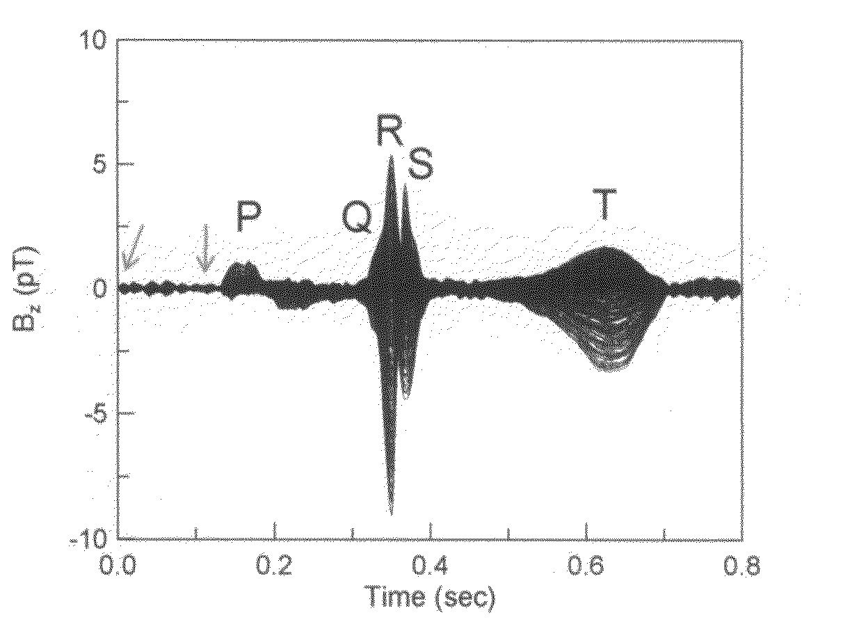
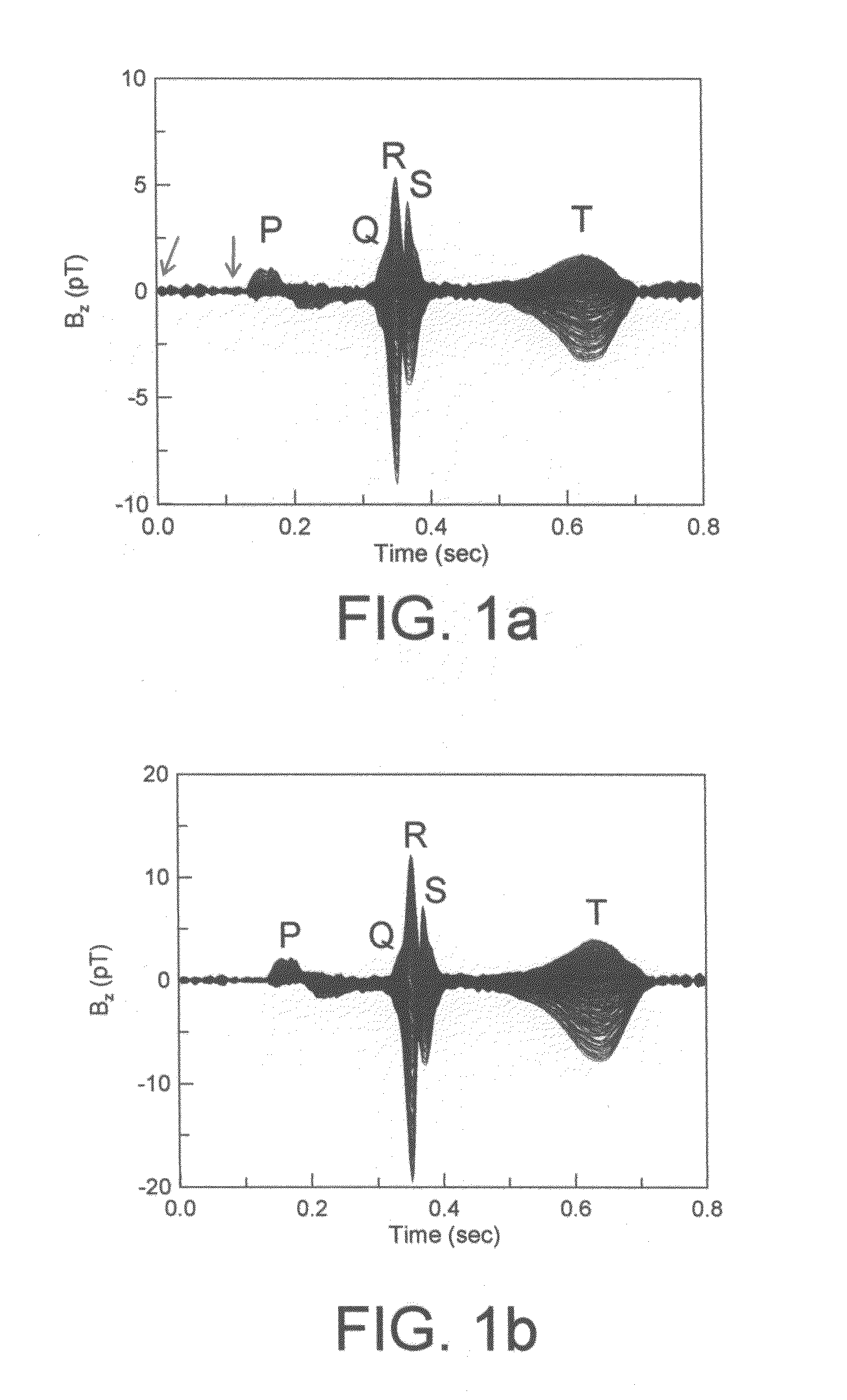
[0049]A multi-channel SQUID system, for example, a 64-channel SQUID system or other type of sensitive superconducting magnetometers, is positioned in a plurality of coordinates, for example in a two-dimension or three-dimensional array slightly above the thorax of a live specimen. Each sensor of the SQUID system registers the local extracorporeal magnet field strength as a function of time. A MCG system normally provides measurement of the magnetic field components perpendicular (z-component) (Bz) to the body surface as a function of time (t). Magnetocardiograph (MCG) has features similar to the P-wave, the QRS complex, the T-wave and the U-wave of the ECG (electrocardiography). FIG. 1(a) is a diagram of Bz-t curves, which are plots of a collection of the spatially distributed magnetocardiac signals along the direction normal to the body surface as a function of time of a study subject using a SQUID MCG system. The collection of the magnetocardiac signals co...


PUM


Abstract

A method of examining cardiac electromagnetic activity over a heart for diagnosing the cardiac functions of the heart is disclosed. The method may include constructing a phase diagram of electromagnetic signals over a heart by collecting sets of time-dependent magnetic signals, determining the zeroth and the first derivations of each set of the magnetic signals at a given time, and categorizing the zeroth and the first derivations of the magnetic signals in either of the four phases: (+, +), (−, −), (+, −), (−, +). The method may also include monitoring a wave propagation of the magnetic signals.

Description

BACKGROUND OF THE INVENTION[0001]1. Field of Invention[0002]The present invention relates to a method of examining dynamic cardiac electromagnetic activity and a detection of cardiac functions using the results thereof. More particularly, the present invention relates to a method of examining the magnetocardiographic signals and a diagnosis of coronary artery diseases using the results thereof.[0003]2. Description of Related Art[0004]Each heart beat is originated from the development a small pulse of electric current that spreads rapidly in the heart and causes the myocardium to contract (depolarization and repolarization). The electrical currents that are generated spread not only within the heart, but also throughout the body, resulting in the establishment of electric potentials on the body surface, which are detectable as changes in the electrical potential with an electrocardiograph (ECG). A typical ECG tracing of a normal heartbeat (or cardiac cycle) consists of a P wave, a PR...

Claims


Application Information

Patent Timeline
Patent Type & Authority Patents(United States)
IPC IPC(8): A61B5/05
CPCA61B5/04007A61B5/7239G06F19/3437G16H50/50A61B5/243
Inventor HORNG, HERNG-ERWU, CHAU-CHUNGYANG, HONG-CHANGYANG, SHIEH-YUEH
Owner HORNG HERNG ER
Why Eureka
Try Eureka