Stabilization and support strut with secure deployment features

a technology of stabilization and support struts, which is applied in the direction of machine supports, rod connections, other domestic objects, etc., can solve the problems of pistons falling out of barrels, lanyards attaching pins to locking studs may prove clumsy in use, and rescuers may be in the way of rescuers

Active Publication Date: 2010-10-05
HALE PRODUCTS INC
View PDF20 Cites 28 Cited by
  • Summary
  • Abstract
  • Description
  • Claims
  • Application Information

AI Technical Summary

Benefits of technology

[0008]The first collar assembly releases the piston for extension and retraction and secures the piston at the correct length. The second collar assembly rotatably secures the barrel and can be locked down to provide a snug fit against the first collar assembly to hold the piston tight in position. When the first collar assembly releases the piston for extension and retraction, the first responder moves the piston axially in the barrel and the first and second collars remain in cooperating secured relation on the barrel. An elastomeric sealing member located at the bottom of the piston precludes the piston from falling out of the barrel and provides for readily reducing the piston length and pneumatically extending the piston. When the piston is in the correct position, the first responder then secures the piston with the first collar assembly, rotatably tightens the second collar assembly against the first, and secures the second collar assembly to the barrel to preclude further rotation and to secure the piston in the correct position.

Problems solved by technology

While successful and secure in use, the tools described above sometimes cause problems in deployment.
If the pins fall out of the holes in the piston during transport or deployment, the piston may fall out of the barrel.
Lanyards attaching pins to the locking studs may prove clumsy in use and get in the rescuers' way.

Method used


Image

  • Stabilization and support strut with secure deployment features
  • Stabilization and support strut with secure deployment features
  • Stabilization and support strut with secure deployment features

Examples


Embodiment Construction

[0025]The invention can best be understood with reference to the specific embodiment that is illustrated in the drawings and the variations described herein below. While the invention will be so described, it should be recognized that the invention in not intended to be limited to the embodiments illustrated in the drawings. On the contrary, the invention includes all alternatives, modifications, and equivalents that may be included within the spirit and scope of the invention as defined by the appended claims.

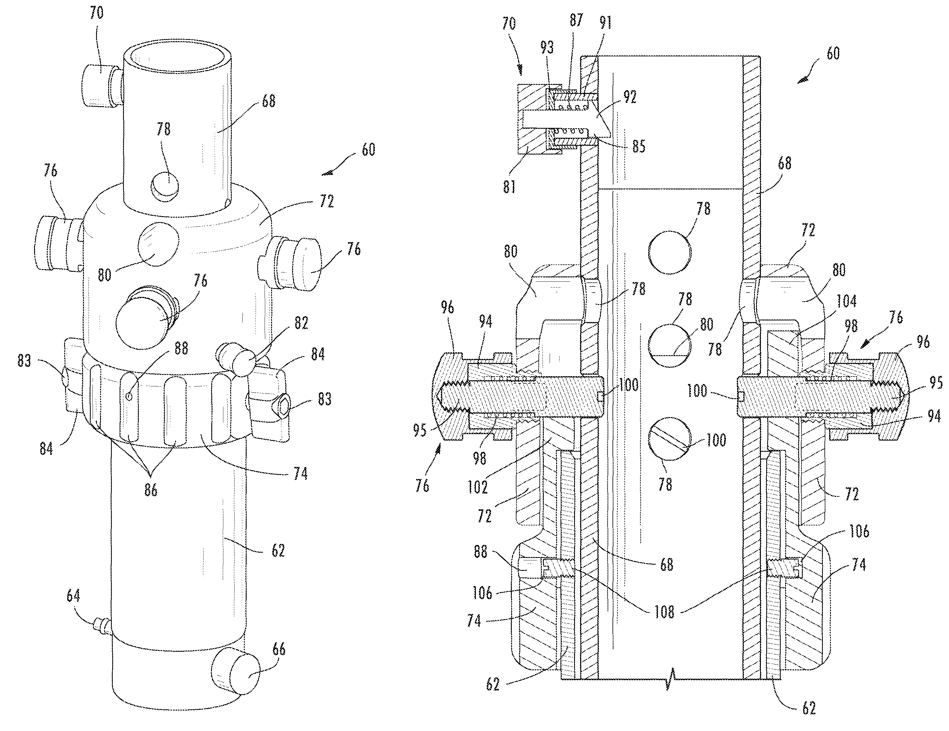
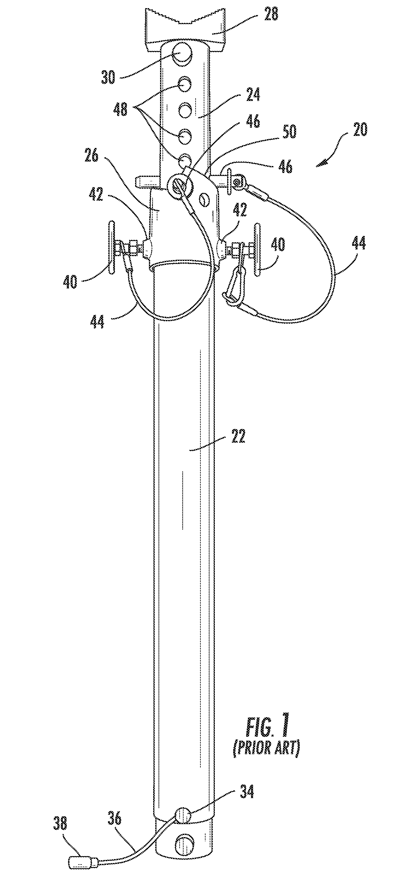
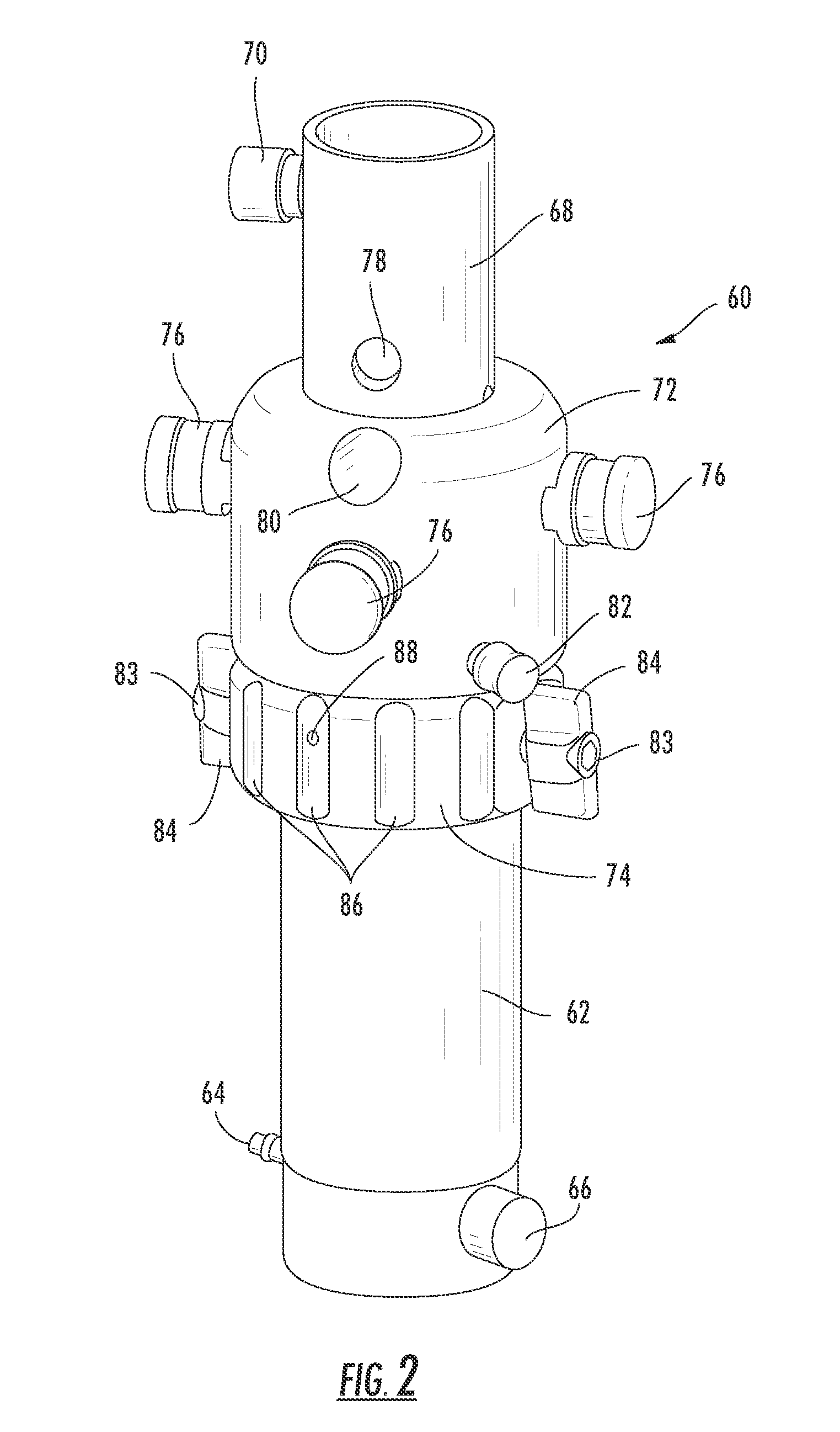
[0026]FIG. 1 illustrates generally at 20 a stabilization and support tool of the prior art, having a barrel 22 and a hollow piston 24 of smaller diameter inserted into the barrel and extending from the barrel. A collar assembly 26 secures the piston against axial movement in the barrel to provide a strut suitable for rescue operations. A V-block 28 is inserted into the upper end of the piston and held in place by a quick disconnect 30. The V-block is stepped on its upper surfa...


PUM


Abstract

A stabilization and support strut for use in rescue operations in buildings, trenches, vehicle accidents, and the like has secure deployment features including first and second inter-fitting collar assemblies, the first collar assembly including a first collar, circumferentially based spring-biased piston-retaining pins mounted in the collar for fitting into orifices in a piston body, and a locking pin for precluding rotation and axial movement of the first collar on the strut; and the second collar assembly including a second collar rotatingly secured on the barrel with a portion of the second collar underlying the first and having a circumferentially inclined ratchet surface for snugly engaging the piston-retaining pins upon rotation of the second collar, the second collar further including rotatable studs for engaging the barrel and precluding rotation of the second collar about the barrel when snug against the piston-retaining pins.

Description

FIELD OF THE INVENTION[0001]This invention relates to stabilization and support apparatus, and, in particular, to apparatus deployed in rescue and recovery operations in buildings, trenches, vehicle accidents, and the like.BACKGROUND OF THE INVENTION[0002]First responders approaching an accident scene typically determine what is of most immediate danger to the victim's life and themselves in rescuing that victim. Reaching the victim safely generally requires an initial assessment of the accident scene followed by stabilization and structural support of surrounding surfaces, whether the accident involves an automobile crash, a potential building collapse, a potential collapse of a wall below grade level, as in a trench, or other hazard of the accident scene. Speed of deployment and set-up are of paramount importance to the first responder.[0003]A variety of tools have been developed over the years for supporting and stabilizing surfaces in rescue operations. These tools can be used t...

Claims


Application Information

Patent Timeline
Patent Type & Authority Patents(United States)
IPC IPC(8): A47F5/00
CPCE04G25/06Y10T403/32467E04G25/061E04G2025/047
Inventor SISK HORNE, TAMMYSULLIVAN, KEVIN
Owner HALE PRODUCTS INC
Why Eureka
Try Eureka