
Piston for a gas-operated firearm

a gas-operated, firearm technology, applied in the field of firearms, can solve the problems of generating malfunctions, insufficient pressure to cycle the action, and excessive pressure, and achieve the effect of improving the appreciation of the contribution to the ar

Active Publication Date: 2018-06-07
KNS PRECISION INC
View PDF1 Cites 11 Cited by
  • Summary
  • Abstract
  • Description
  • Claims
  • Application Information

AI Technical Summary

Benefits of technology

The present invention provides an improved piston for a gas-operated firearm that has all the advantages of the prior art. It includes an elongated body with a head portion that can transmit an operating force to the action in response to gas pressure on the first side and has a bypass passage with an adjustment facility to provide selectable resistance to gas flow through the bypass passage. The invention has a movable occlusion element that can selectably occlude the bypass passage. The technical effect of the invention is to improve the performance and reliability of gas-operated firearms by allowing them to operate in a more efficient and effective manner.

Problems solved by technology

Excessive pressure generates unwanted wear and potential damage to components, if the energy is well more than that needed to cycle the action.
Inadequate pressure may be insufficient to cycle the action, and generate malfunctions.
However, when users wish to change some aspect of the application, they may face major tasks to modify or replace major components on their rifle to provide a suitable gas flow.
While these traditional approaches are effective at controlling movement of the action, the use of a sound suppressor or specialized ammunition with a firearm can result in excessive gas pressure that accelerates wear and adversely affects accuracy.
While some firearms have gas blocks that can be replaced with alternatives that reduce the gas pressure, some firearms have permanently-mounted gas blocks or gas blocks that are difficult to remove.

Method used


Image

  • Piston for a gas-operated firearm
  • Piston for a gas-operated firearm
  • Piston for a gas-operated firearm

Examples


Embodiment Construction

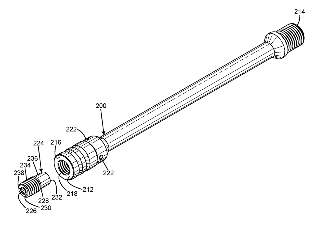
[0019]An embodiment of the piston for a gas-operated firearm of the present invention is shown and generally designated by the reference numeral 10.

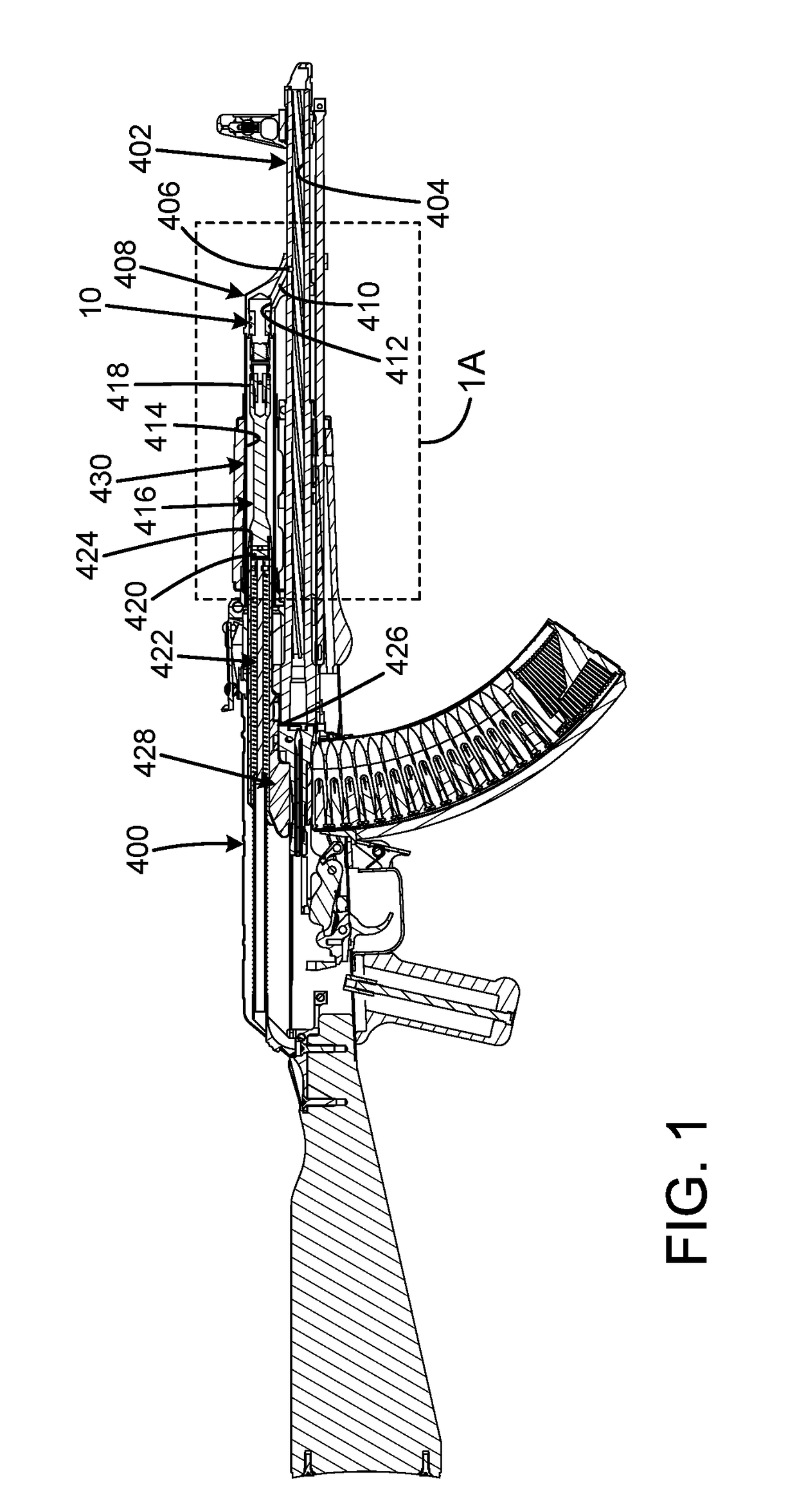
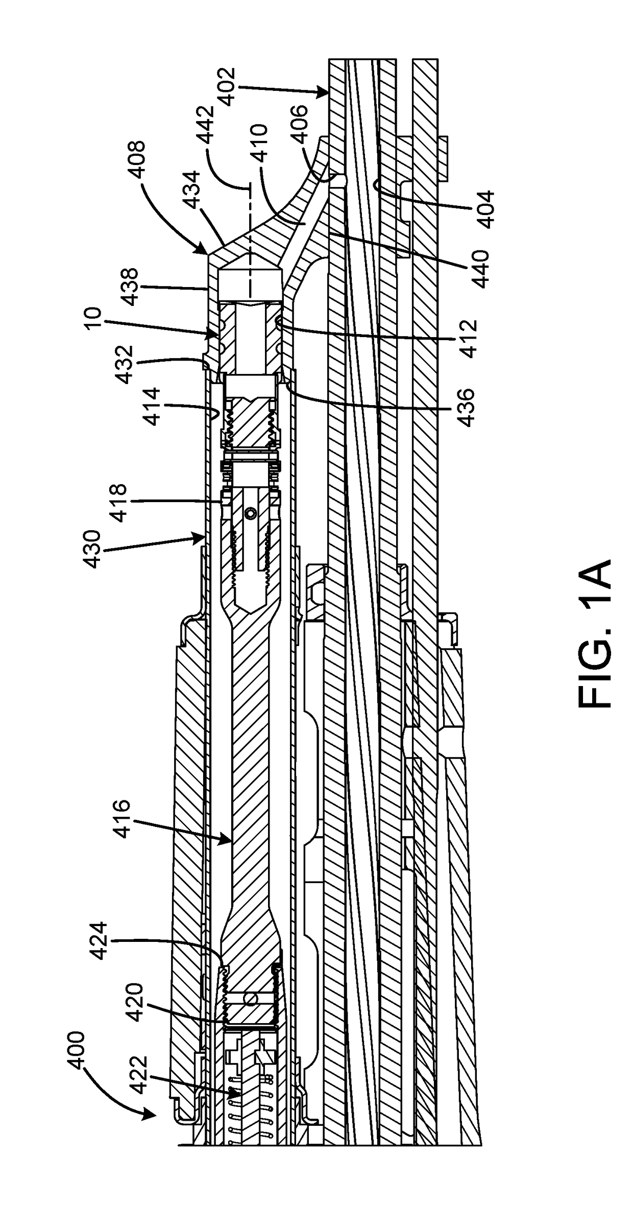
[0020]FIGS. 1 and 1A illustrate the improved piston for a gas-operated firearm 10 of the present invention. More particularly, the piston for a gas-operated firearm is shown installed in a rifle 400. The rifle 400 has a barrel 402 that defines a central barrel bore 404. A gas port 406 is in fluid communication with the central barrel bore 404. A gas block 408 is attached to the barrel. The gas block has a gas passage 410 that enables fluid communication between the gas port and a rearward-facing cylindrical central bore 412 that defines a bore axis 442 and flares at the rear 436. A tube 430 has a central bore 414 that is in fluid communication with the central bore 412. The piston 10 is an elongated body having a front piston head portion 106 received within the central bore 412 of the gas block and the central bore 414 of the tube for r...


PUM


Abstract

A piston for a gas-operated firearm has an elongated body having a head portion adapted to be closely received in the cylindrical bore for reciprocation within the bore, the head portion having a first side toward a forward direction and a second side toward the rearward direction, the body having an operational facility on the second side adapted to transmit an operating force to the action in response to gas pressure on the first side, and the head portion defining a bypass passage between the first side and the second side. The bypass passage may have an adjustment facility adapted to provide selectable resistance to gas flow through the bypass passage. The adjustment facility may be a movable occlusion element that selectably occludes the bypass passage. The occlusion element may be a threaded element. The occlusion element may be a collar that receives a portion of the body.

Description

CROSS-REFERENCE TO RELATED APPLICATIONS[0001]This application claims the benefit of U.S. Provisional Patent Application No. 62 / 428,643 filed on Dec. 1, 2016, entitled “PISTON-BASED METHOD OF GAS REGULATION FOR SELF-LOADING FIREARMS,” and also claims the benefit of U.S. Provisional Patent Application No. 62 / 525,546 filed on Jun. 27, 2017, entitled “METHODS FOR VENTING EXCESS GAS THROUGH AND / OR AROUND A PISTON,” which are hereby incorporated by reference in its entirety for all that is taught and disclosed therein.FIELD OF THE INVENTION[0002]The present invention relates to firearms, and more particularly to a piston for a gas-operated firearm that is tunable to control how much energy from the expanding gas is converted into motion to cycle the firearm.BACKGROUND OF THE INVENTION[0003]Gas-operated firearms utilize a portion of the high-pressure gas resulting from the discharge of a cartridge to cycle the action of the firearm. The portion of high-pressure gas typically exits via a po...

Claims


Application Information

Patent Timeline
Patent Type & Authority Applications(United States)
IPC IPC(8): F41A5/20F41A5/28
CPCF41A5/20F41A5/28
Inventor RODE, NICHOLAS ADAMFISHER, DANIEL EARLWELCH, CHRISTIAN KAGER
Owner KNS PRECISION INC
Learn More