Method for improving spatial index efficiency by jittering splitting planes

a spatial index and jittering technology, applied in the field of image processing, can solve the problems of rasterization suffering from some drawbacks, modern monitors display images, and use relatively low amounts of computational power

Active Publication Date: 2010-10-05
ACTIVISION PUBLISHING
View PDF13 Cites 98 Cited by
  • Summary
  • Abstract
  • Description
  • Claims
  • Application Information

AI Technical Summary

Problems solved by technology

One limitation of rendering realistic images is that modern monitors display images through the use of pixels.
Rasterization is effective at rendering graphics quickly and using relatively low amounts of computational power; however, rasterization suffers from some drawbacks.
For example, rasterization often suffers from a lack of realism because it is not based on the physical properties of light, rather rasterization is based on the shape of three-dimensional geometric objects in a scene projected onto a two dimensional plane.
Furthermore, the computational power required to render a scene with rasterization scales directly with an increase in the complexity of the scene to be rendered.
As image processing becomes more realistic, rendered scenes also become more complex.
Therefore, rasterization suffers as image processing evolves, because rasterization scales directly with complexity.
Furthermore, ray tracing also handles increases in scene complexity better than rasterization as scenes become more complex.
This is due to the fact that the same number of rays may be cast into a scene, even if the scene becomes more complex.
One major drawback of ray tracing is the large number of calculations, and thus processing power, required to render scenes.
This leads to problems when fast rendering is needed.
Due to the increased computational requirements for ray tracing it is difficult to render animation quickly enough to seem realistic (realistic animation is approximately twenty to twenty-four frames per second).

Method used


Image

  • Method for improving spatial index efficiency by jittering splitting planes
  • Method for improving spatial index efficiency by jittering splitting planes
  • Method for improving spatial index efficiency by jittering splitting planes

Examples


Embodiment Construction

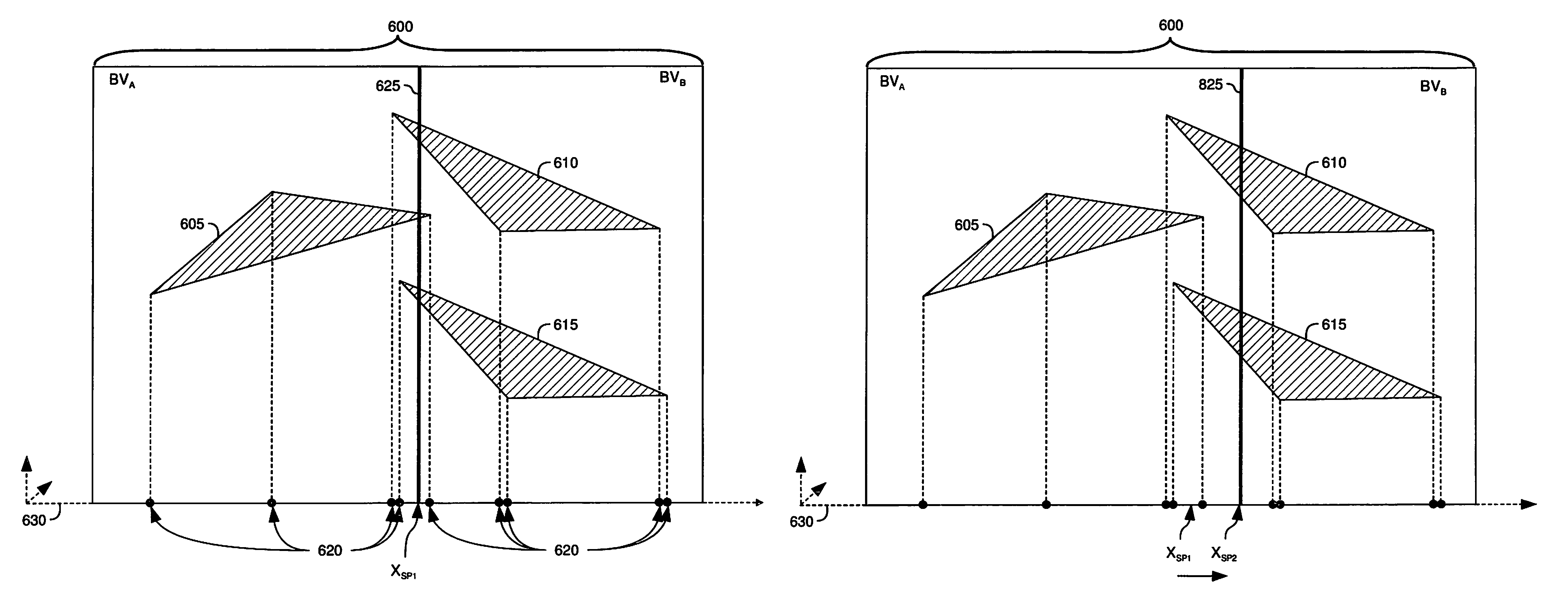
[0024]Embodiments of the invention provide methods and apparatus to improve the efficiency of a ray tracing image processing system. According to one embodiment of the invention, the position of a splitting plane used to create a bounding volume may be modified in both a positive and negative direction along an axis to determine if a more efficient location for the splitting plane exists. After a modification in either direction a number of primitives intersected by the splitting plane may be calculated. The number of primitives intersected by the splitting plane for each location (e.g., modified location in positive direction, modified location in negative direction, or original location) may be compared, and the location with the fewest intersected primitives may be chosen for the final position of the splitting plane. By choosing the location with the fewest intersected primitives the efficiency of the image processing system may be improved.

[0025]In the following, reference is m...


PUM


Abstract

Embodiments of the invention provide methods and apparatus to improve the efficiency of a ray tracing image processing system. According to one embodiment of the invention, when building a spatial index the position of a splitting plane used to create a bounding volume may be jittered or moved along an axis to determine if a more efficient location for the splitting plane exists. After jittering the splitting plane a number of primitives intersected by the splitting plane may be calculated. The number of primitives intersected by the splitting plane for each location may be compared, and the location with the fewest intersected primitives may be chosen for the final position of the splitting plane. By choosing the location with the fewest intersected primitives the number of ray-primitive intersection tests necessary when performing ray tracing may be reduced. Consequently, the efficiency of the image processing system may be improved.

Description

BACKGROUND OF THE INVENTION[0001]1. Field of the Invention[0002]Embodiments of the invention generally relate to the field of image processing.[0003]2. Description of the Related Art[0004]The process of rendering two-dimensional images from three-dimensional scenes is commonly referred to as image processing. As the modern computer industry evolves image processing evolves as well. One particular goal in the evolution of image processing is to make two-dimensional simulations or renditions of three-dimensional scenes as realistic as possible. One limitation of rendering realistic images is that modern monitors display images through the use of pixels.[0005]A pixel is the smallest area of space which can be illuminated on a monitor. Most modern computer monitors will use a combination of hundreds of thousands or millions of pixels to compose the entire display or rendered scene. The individual pixels are arranged in a grid pattern and collectively cover the entire viewing area of the...

Claims


Application Information

Patent Timeline
Patent Type & Authority Patents(United States)
IPC IPC(8): G06T17/00G06T15/60G06T15/50G06T15/40G06T15/00G06T9/00G06F12/02
CPCG06T15/06G06T15/40
Inventor SHEARER, ROBERT ALLEN
Owner ACTIVISION PUBLISHING
Why Eureka
Try Eureka