Locking connector

a technology of locking connectors and connectors, applied in the direction of coupling device connections, securing/insulating coupling contact members, electrical devices, etc., can solve the problems of posing an annoyance for use or assembly, and achieve the effect of stable positioning

Inactive Publication Date: 2010-10-12
AIMMET IND
View PDF5 Cites 12 Cited by
  • Summary
  • Abstract
  • Description
  • Claims
  • Application Information

AI Technical Summary

Benefits of technology

[0005]The object of this invention is to offer a connector that has a body combined with a terminal base in a first stag

Problems solved by technology

However, as the terminal base of the conventional connector is formed circular, it is to freely rotate aft

Method used


Image

  • Locking connector
  • Locking connector
  • Locking connector

Examples


Embodiment Construction

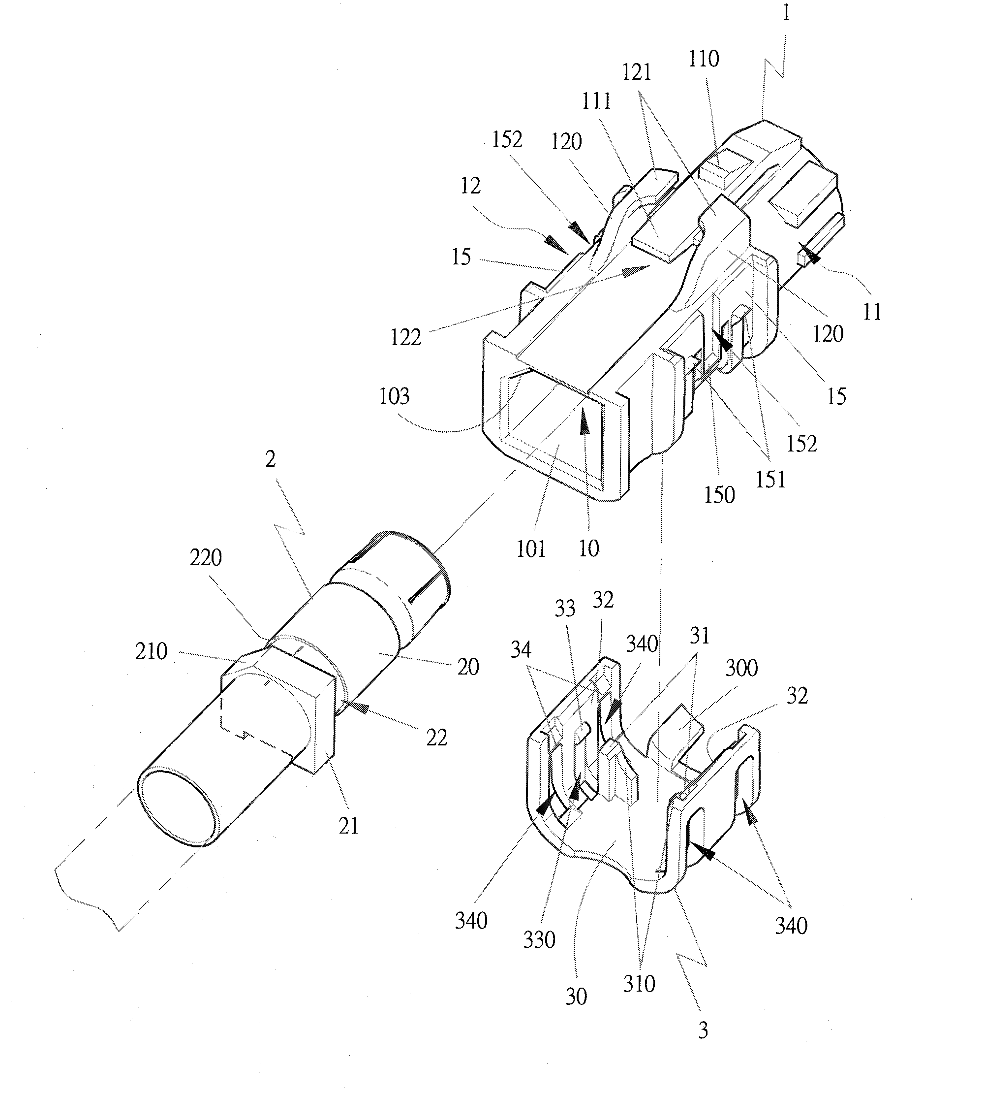
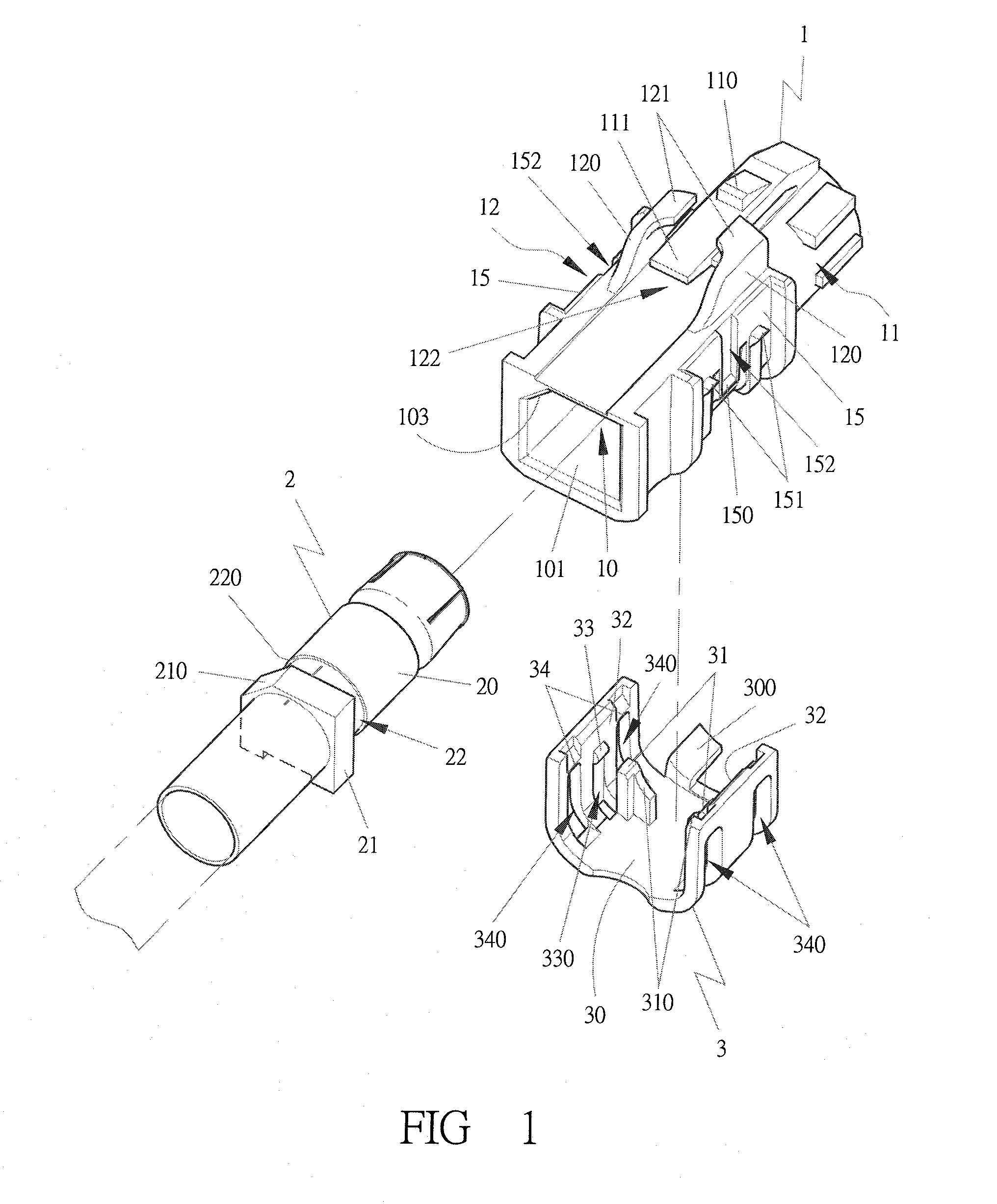
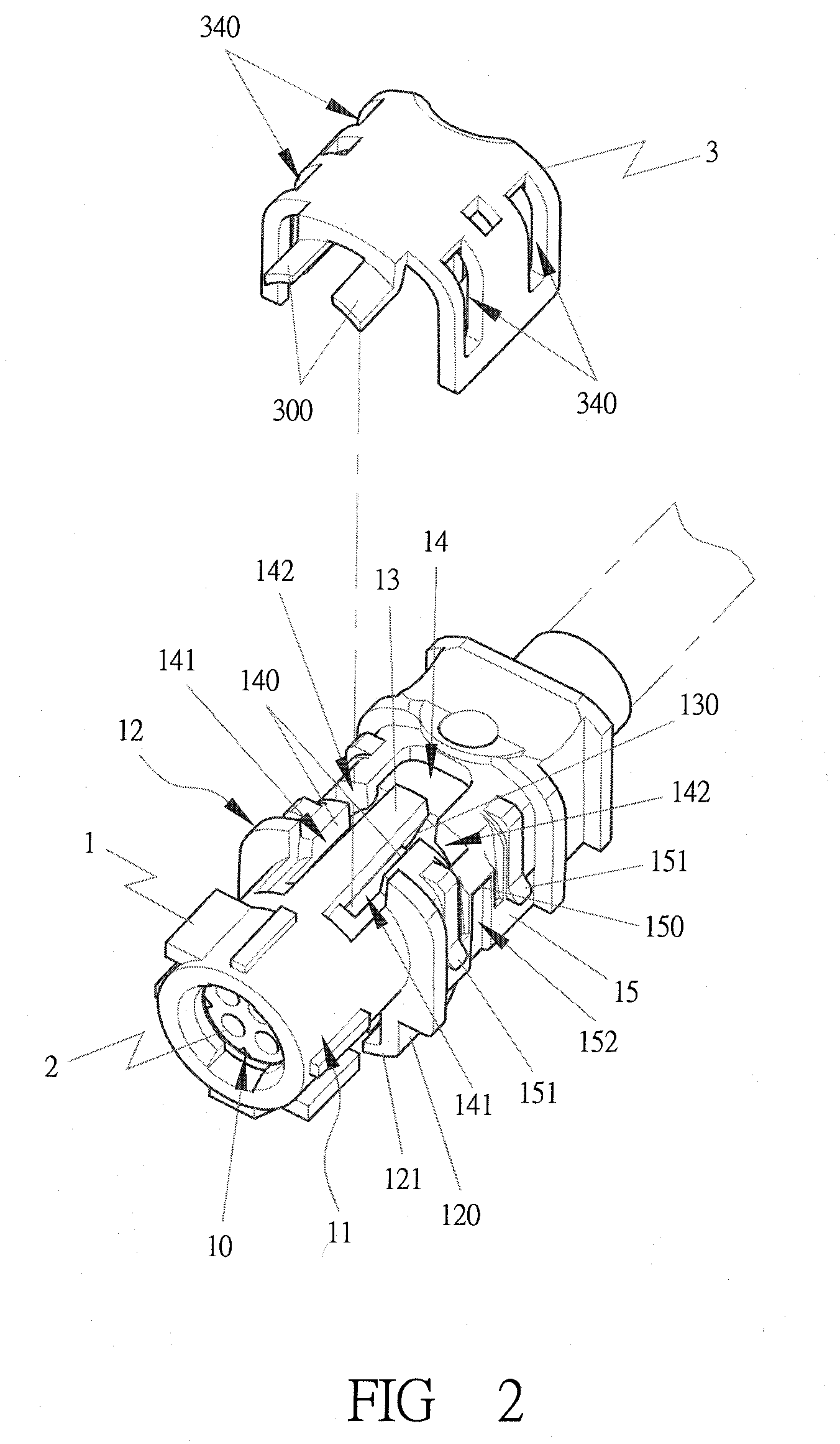
[0029]As shown in FIGS. 1˜4, a preferred embodiment of a connector in the present invention includes at least a body1, a terminal base 2 and a fixing base 3.

[0030]The body 1 has a terminal base groove 10 consisting of a circular portion 100 and a square portion 101, with a variable length ratio for the circular portion 100 and the square portion 101 depending on practical requirement and the shape of the terminal base 2. A blocking circumference 102 is provided between the circular portion 100 and the square portion 100, as shown in FIG. 4, so that there is a limited depth for the terminal base 2 to be inserted in the terminal base groove 10. Further the square portion 101 of the terminal base groove 10 has an inclined surface to suit to the profile of the terminal base 2 for smoothly directing the terminal base 2 to combine with the terminal base groove 10, so as to avoid the problem that a terminal may be misplaced.

[0031]The body 1 is further constituted of a front portion 11 and ...


PUM


Abstract

A connector includes a body, a terminal base and a fixing base. The body has a terminal base groove consisting of a circular portion and a square portion suited to the profile of the terminal base. A protective base is provided to protect a first tenon from erroneously touched. A second tenon is utilized to engage with an annular recessed groove of the terminal base to combine the body with the terminal base in a first stage. The body has two sides having a first engaging projecting member and plural second engaging projecting members for engaging with those of the fixing base to complete a two-step engagement to enable the body, the terminal base and the fixing base combined together. The fixing base includes plural projecting-out rods and projecting-up rods to make the body combined with the fixing base, facilitating the connector conveniently assembled.

Description

BACKGROUND OF THE INVENTION[0001]1. Field of the Invention[0002]This invention relates to a connector, particularly to one employing a second tenon provided in a body to initially combine with a terminal base before combining the body with the terminal base by means of a fixing base, enabling the connector assembled easily and conveniently.[0003]2. Description of the Prior Art[0004]A conventional connector, such as the one disclosed in Taiwan Patent No. 234316 on Jun. 11, 2005 and authorized to this applicant, mainly includes a body having a terminal base groove formed inside for accommodating a terminal base. The terminal base groove is provided with a calibrating groove located in a front circumference. The body also has a tenon formed in a tenon groove that is extended backward to integrate with the body so as to form a connecting rib and a pressing grip. A plurality of petals are formed around the rear side of the terminal base groove for combining with the terminal base. The te...

Claims


Application Information

Patent Timeline
IPC IPC(8): H01R13/40
CPCH01R13/42H01R13/447H01R13/506Y10S439/903
Inventor CHEN, HSIANG FENG
Owner AIMMET IND
Why Eureka
Try Eureka