
Metal detector

a metal detector and detector technology, applied in the field of detectors, can solve the problems of reducing the detection accuracy of metal detectors, reducing the production cost of metal detectors, and complicated and expensive conventional metal detectors

Inactive Publication Date: 2010-10-19
HONG FU JIN PRECISION IND (SHENZHEN) CO LTD +1
View PDF1 Cites 5 Cited by
  • Summary
  • Abstract
  • Description
  • Claims
  • Application Information

AI Technical Summary

Benefits of technology

[0005]Generally speaking, a conventional metal detector includes a transmitting coil, a receiving coil, an oscillator, a cymoscope, a processor, a transducer, and so on. The processor identifies and processes signals generated by the receiving coil, the oscillator, and the cymoscope, and then signals the transducer to output an audible sound according to the processing result. The conventional metal detector is very complicated and expensive, therefore it is not feasible for mass production and adopted widely throughout the various industries. Moreover, analogue signals such as current signals, are easily influenced by the environmental factors while transmitting, thus reducing the accuracy of the detecting results.

Problems solved by technology

The conventional metal detector is very complicated and expensive, therefore it is not feasible for mass production and adopted widely throughout the various industries.
Moreover, analogue signals such as current signals, are easily influenced by the environmental factors while transmitting, thus reducing the accuracy of the detecting results.

Method used


Image

  • Metal detector
  • Metal detector
  • Metal detector

Examples


Embodiment Construction

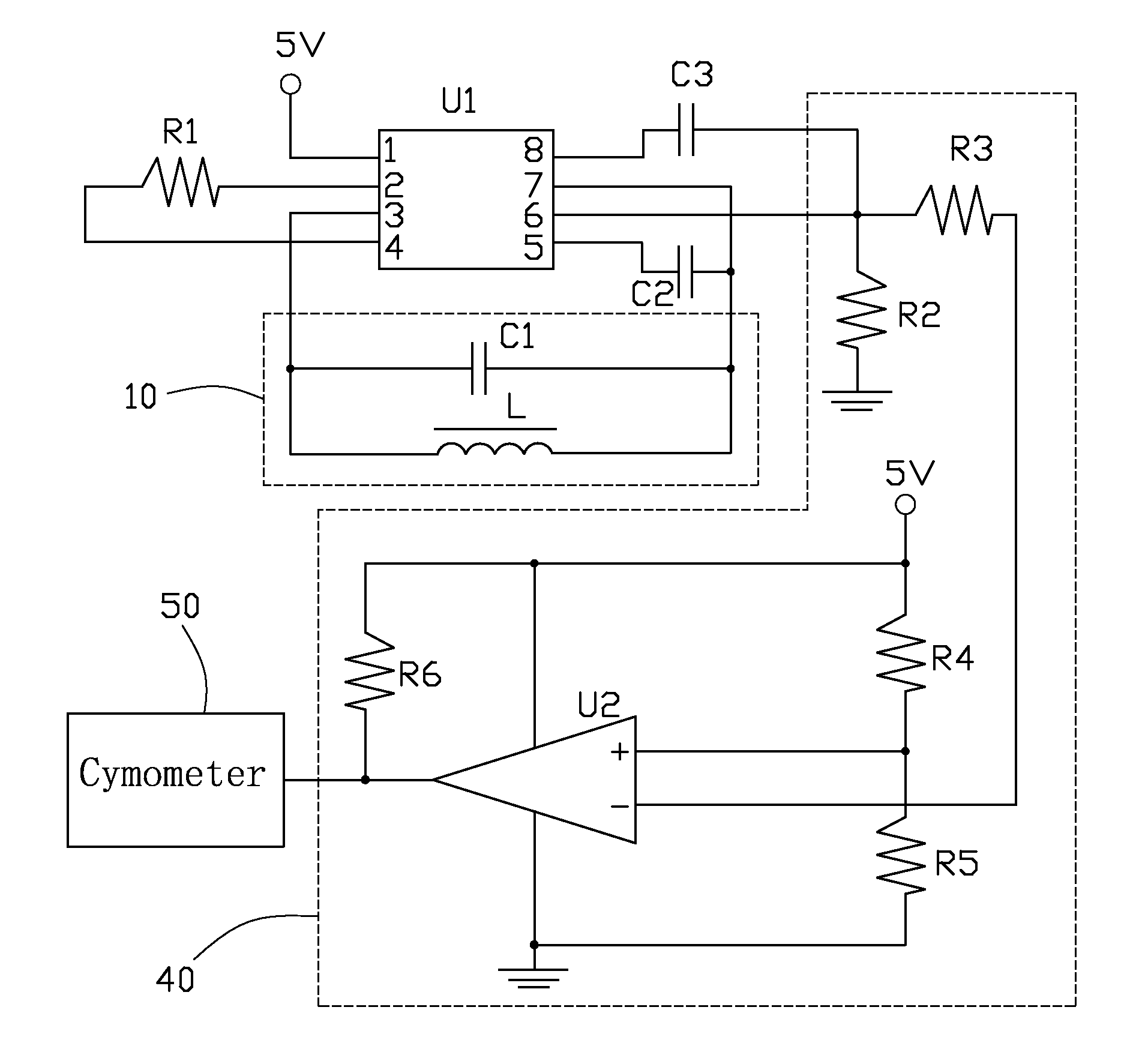
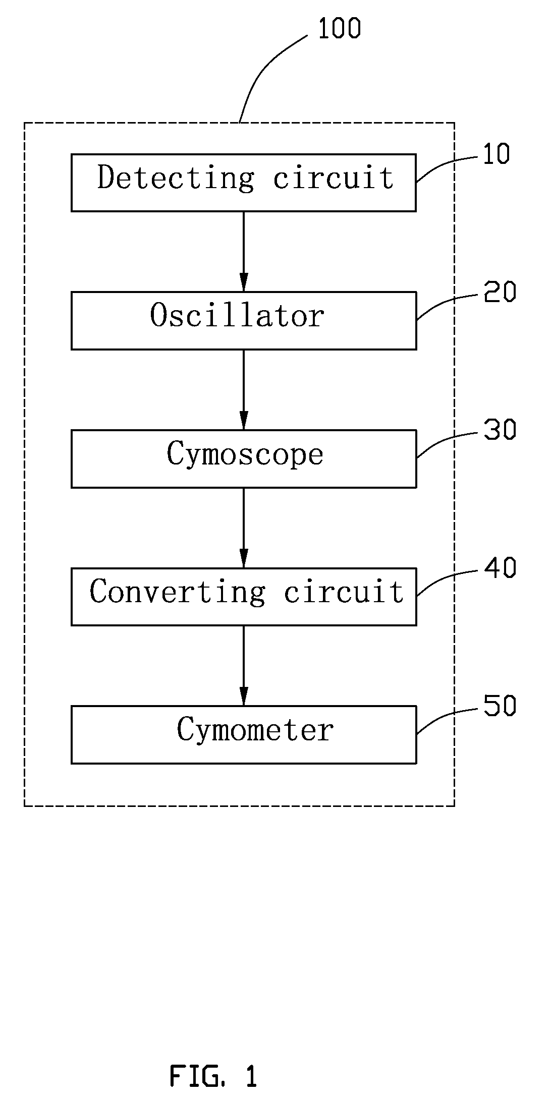
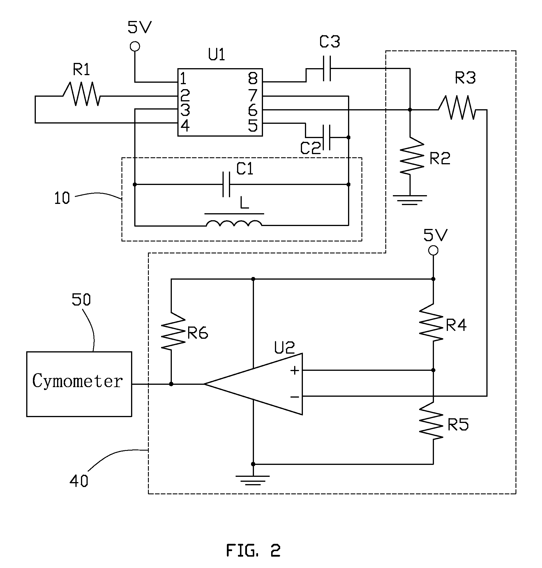
[0009]Referring to FIG. 1, a metal detector 100 in accordance with an embodiment of the present invention includes a detecting circuit 10, an oscillator 20, a cymoscope 30, a converting circuit 40, and a cymometer 50. The detecting circuit 10, the oscillator 20, and the cymoscope 30 work together to generate a current signal to the converting circuit 40, the converting circuit 40 transforms the current signal to a voltage signal and transmits the voltage signal to the cymometer 50, and the cymometer 50 displays a value of a frequency of the current signal according to the voltage signal.

[0010]Referring to FIG. 2, the detecting circuit 10 includes an inductance coil L and a capacitor C1. The oscillator 20 and the cymoscope 30 are integrated in a single chip micyoco (SCM) U1, and the SCM U1 includes a power supply terminal 1, two regulating terminals 2, 4, two detecting terminals 3, 7, a filtering terminal 5, an output terminal 6, and a coupling terminal 8. The inductance coil L and a...


PUM


Abstract

An exemplary metal detector includes a detecting circuit, a SCM, a converting circuit, and a cymometer. The SCM cooperates with the detecting circuit to generate a current signal with a specific frequency, the converting circuit transforms the current signal received from the SCM to a voltage signal, and the cymometer displays a value of a frequency of the current signal according to the voltage signal. When the detecting circuit detects a metal nearby, the value of the frequency of the current signal displayed on the cymometer changes.

Description

BACKGROUND[0001]1. Field of the Invention[0002]The present invention relates to a detector, and particularly to a metal detector for detecting metal objects.[0003]2. Description of the Related Art[0004]Nowadays, metal detectors are used in various fields and are based on the measurement of changes in the electromagnetic field, which are brought about by metal objects located in a zone to be monitored. Metal detectors are used in the security inspections, such as checking passengers at airports, checking visitors in particularly highly protected buildings or installations. Metal detectors are also used for a wide range of purposes in industry.[0005]Generally speaking, a conventional metal detector includes a transmitting coil, a receiving coil, an oscillator, a cymoscope, a processor, a transducer, and so on. The processor identifies and processes signals generated by the receiving coil, the oscillator, and the cymoscope, and then signals the transducer to output an audible sound acc...

Claims


Application Information

Patent Timeline
Patent Type & Authority Patents(United States)
IPC IPC(8): G01V3/08
CPCG01V3/104G01V3/15
Inventor QIN, QIANGLIU, TIAN-YOUGONG, LIAN-ZHONG
Owner HONG FU JIN PRECISION IND (SHENZHEN) CO LTD
Learn More