Method and system for cleaning magnetic artifacts using a carbonyl reactive ion etch

a carbonyl reactive ion etch and magnetic artifact technology, applied in the field of magnetic recording technology, can solve the problems of compromising the performance and reliability, and the performance of the conventional magnetic structure b>10/b> is thus compromised

Inactive Publication Date: 2010-10-26
WESTERN DIGITAL TECH INC
View PDF10 Cites 154 Cited by
  • Summary
  • Abstract
  • Description
  • Claims
  • Application Information

AI Technical Summary

Problems solved by technology

Consequently, performance and reliability may be compromised.
Perfor

Method used


Image

  • Method and system for cleaning magnetic artifacts using a carbonyl reactive ion etch
  • Method and system for cleaning magnetic artifacts using a carbonyl reactive ion etch
  • Method and system for cleaning magnetic artifacts using a carbonyl reactive ion etch

Examples


Embodiment Construction

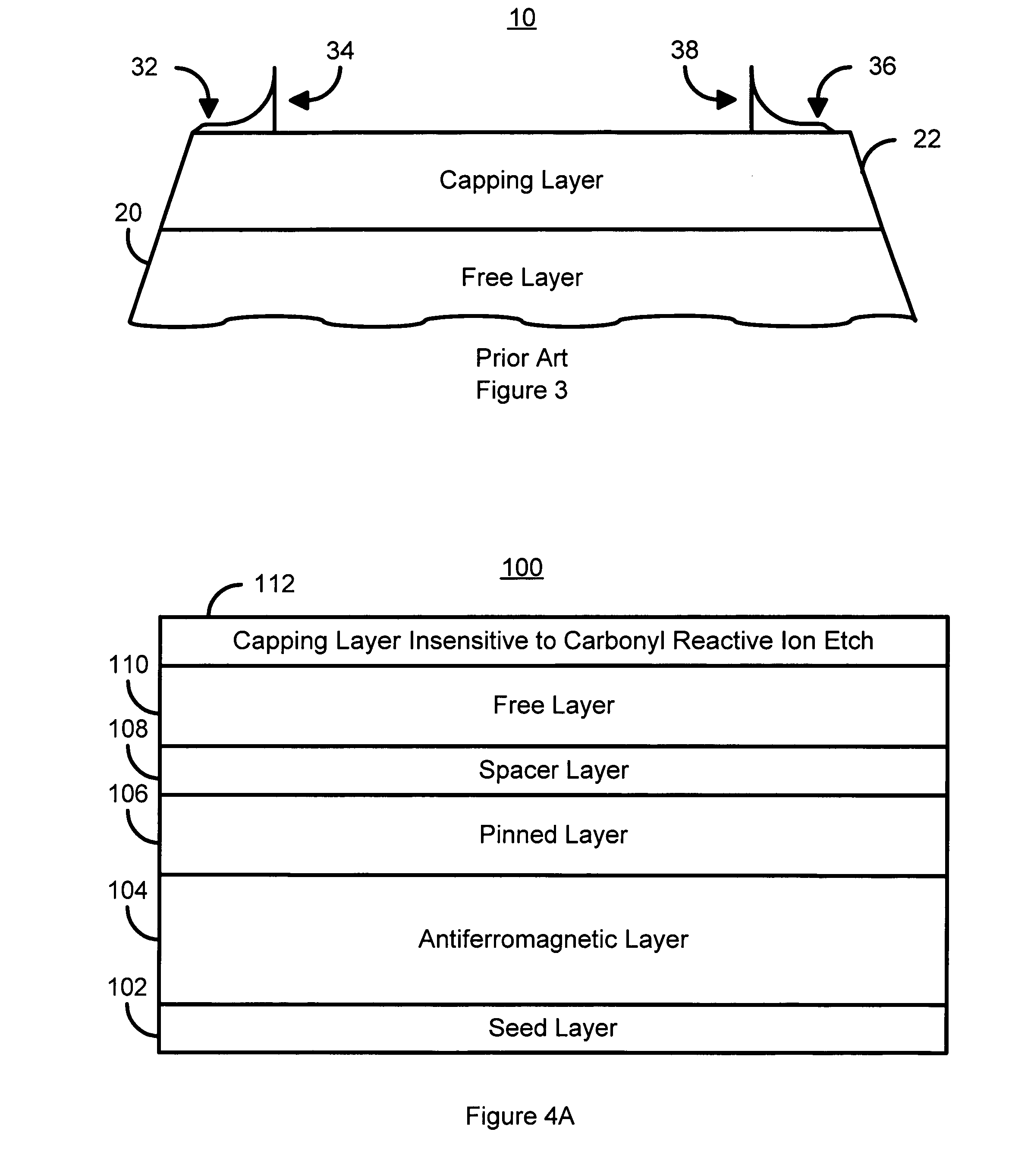
[0013]FIGS. 4A-4F depict a magnetic structure 100 formed in accordance with an exemplary embodiment of the present invention. The magnetic structure 100 is a spin valve. However, the method and system of the present invention may be used with other magnetic structures and other applications including, but not limited to, tunneling magnetoresistive junctions and magnetic random access memories. Furthermore, for clarity, FIGS. 4A-4F are not drawn to scale. Referring to FIG. 4A, the magnetic structure 100 is from a number of layers, at least one of which includes a magnetic material. In the embodiment of the magnetic structure 100 shown, the layers include a seed layer 102, an AFM layer 104, a pinned layer 106, a spacer layer 108, a free layer 110 and a capping layer 112. The pinned layer 106 and free layer 110 are magnetic. The spacer layer 108 is a thin, nonmagnetic conductor. The capping layer 112 is the top layer of the magnetic structure 100 and is insensitive to an isotropic carb...


PUM

PropertyMeasurementUnit
Timeaaaaaaaaaa
Timeaaaaaaaaaa
Timeaaaaaaaaaa

Abstract

A method and system for providing a magnetic structure that includes at least one magnetic material is disclosed. The method and system include defining the magnetic structure. The magnetic structure also includes a top layer that is insensitive to an istroropic carbonyl reactive ion etch. The defining of the magnetic structure results in at least one artifact. The method and system further includes cleaning the at least one artifact using at least one isotropic carbonyl reactive ion etch.

Description

FIELD OF THE INVENTION[0001]The present invention relates to magnetic recording technology, and more particularly to a method and system for cleaning processing artifacts on magnetic structures.BACKGROUND OF THE INVENTION[0002]FIG. 1 depicts a conventional magnetic structure 10. The conventional magnetic structure 10 depicted is a spin valve that exhibits giant magnetoresistance. The conventional magnetic structure 10 includes a seed layer 12, an antiferromagnetic (AFM) layer 14, a pinned layer 16, a conventional spacer layer 18, a conventional free layer 20, and a capping layer 22. The conventional pinned layer 18 and the conventional free layer 20 are typically ferromagnetic. The conventional magnetic structure 10 is typically used for reading data.[0003]FIG. 2 depicts a conventional method 50 for providing the conventional magnetoresistive structure 10. Referring to FIGS. 1 and 2, the layer(s) 12, 14, 16, 18, 20, and 22 for the conventional magnetic structure are fabricated, via ...

Claims


Application Information

Patent Timeline
IPC IPC(8): B08B7/00B08B7/04
CPCB82Y25/00B82Y40/00G01R33/098H01F10/3254H01F10/3268H01F41/308H01F41/32G11B5/84G11C11/161
Inventor CHEN, BENJAMINLI, YUN-FEIHINER, HUGH C.ZHANG, WEICHEN, YINGJIAN
Owner WESTERN DIGITAL TECH INC
Why Eureka
Try Eureka