
High stroke sensitivity suspension with laminate load beam for additive laminated and other interconnect support

Active Publication Date: 2010-10-26
MAGNECOMP
View PDF4 Cites 44 Cited by
  • Summary
  • Abstract
  • Description
  • Claims
  • Application Information

AI Technical Summary

Benefits of technology

[0006]Both desired resonance frequency and stroke sensitivity are achieved in the invention even in 11-mm Pico format suspensions as well as the smaller Femto form factor suspensions. Using an outer layer of a suspension laminate bent into an arcuate, “C”, shape eases bending resistance and results in greater stroke distance. Use of a thin laminate layer rather than the usual single element load beam adds to stroke sensitivity as well. Further, use of a thickness-tailored an outer layer of the suspension laminate as the suspension spring, allows close dimensioning of the spring for better spring rates without the drawbacks inherent in etching to a thickness. Since the spring is integral with the laminate portion mounted by the mounting plate, a welding step is not required and typical welding problems such as heating distortions and added production time and costs are avoided. Spring rate is controlled and resonance frequency is also controlled in the invention suspension.
[0007]It is an object therefore of the present invention to provided an improved disk drive suspension. It is a further object to provided a suspension load beam formed from a laminate of first and second outer layers joined by an inner layer of plastic and supporting an electrical interconnect such as an additive type laminate that can be a flexible circuit with or without a metal layer. A further object is the provision of a microactuated suspension having increased stroke sensitivity through the use of a relatively thin laminate first or second outer layer to define the relatively shiftable suspension base and beam portions and to have even these easier bending parts locally arcuately shaped centrally of the base portion and at the edges for less resistance to bending and easier beam portion lateral shifting to position a slider at a disk track. Another object includes defining a stiffener, e.g. with one laminate outer layer, and the beam portion with another laminate outer layer that can also define the suspension spring portion, and having local arcuate shapes in the first or second outer laminate layer. Still another object includes providing flexure adjustment at the distal terminus of the suspension by defining bendable tabs whose repositioning adjusts the flexure.

Problems solved by technology

Using an outer layer of a suspension laminate bent into an arcuate, “C”, shape eases bending resistance and results in greater stroke distance.

Method used


Image

  • High stroke sensitivity suspension with laminate load beam for additive laminated and other interconnect support
  • High stroke sensitivity suspension with laminate load beam for additive laminated and other interconnect support
  • High stroke sensitivity suspension with laminate load beam for additive laminated and other interconnect support

Examples


Embodiment Construction

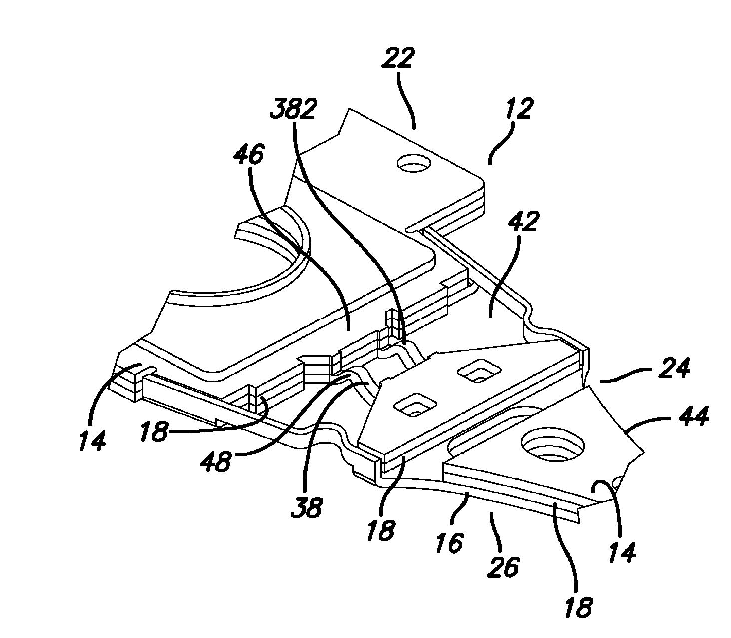
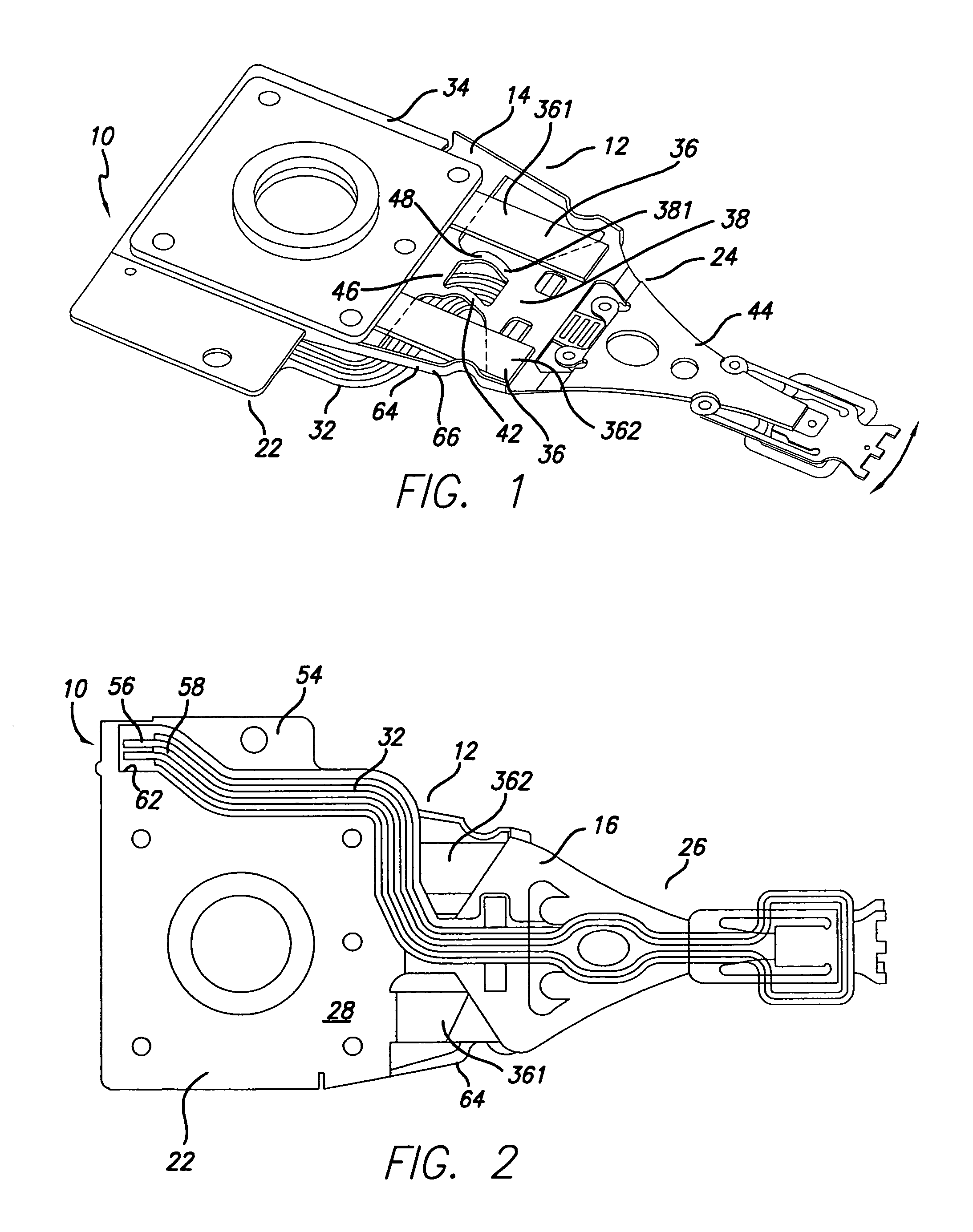
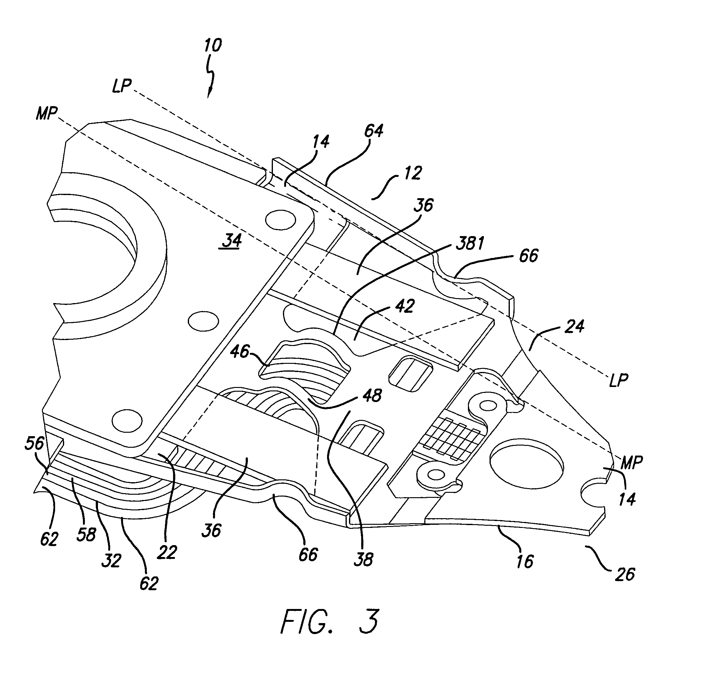
[0050]With reference now to the drawings in detail, in which like numerals indicate like parts in the several views, in FIG. 1 (including FIGS. 2-4), 5 (including FIGS. 6-8), 9 (including FIGS. 10-11) and 12 (including FIGS. 13-15) a high stroke sensitivity microactuated disk drive suspension 10 is shown comprising a laminate 12 extending in a plane LP-LP. Laminate 12 comprises first and second outer layers 14, 16 respectively and a plastic inner layer 18. Suspension 10 then has a base portion 22 comprising the first outer layer 14, a spring portion 24 comprising the first or second outer layer 14, 16, and a beam portion 26 comprising the first and / or second outer layers 14, 16. Suspension 10 has a first side 28 for supporting a flexible circuit electrical interconnect 32 and a second oppositely facing side 34. Suspension 10 further has a microactuator 36 operatively coupled between the base portion 22 and the beam portion 26 for laterally shifting the beam portion (see arrows). Bas...


PUM


Abstract

A high stroke sensitivity microactuated disk drive suspension includes a microactuator, a laminate of first and second outer layers and a plastic inner layer that define a base portion, a spring portion and a beam portion. The base portion has proximate and distal regions coupled by a segment of an outer layer and fixed to the microactuator for relative shifting of the beam portion to the base portion. The segment has a part that is locally arcuate and readily bendable during said shifting for low resistance to shifting giving the suspension high stroke sensitivity.

Description

CROSS-REFERENCE TO RELATED APPLICATIONS[0001]This application claims the benefit of U.S. Provisional Application Ser. No. 60 / 680,646, filed May 12, 2005.BACKGROUND OF THE INVENTION[0002]1. Field of the Invention[0003]This invention relates to disk drive suspensions, and more particularly to microactuated smaller form factor suspensions where stroke sensitivity, that is size of displacement by the microactuators, has been inadequate.[0004]2. Description of the Related Art[0005]Stroke sensitivity and suspension resonance frequency are among the most important desiderata in piezo-electric micro-actuator suspension design. Presently available designs achieving desired resonance frequencies do not achieve the desired stroke sensitivity, and vice-versa. Typically, stroke is not high enough if the suspension is 11 mm long or less.BRIEF SUMMARY OF THE INVENTION[0006]Both desired resonance frequency and stroke sensitivity are achieved in the invention even in 11-mm Pico format suspensions as...

Claims


Application Information

Patent Timeline
IPC IPC(8): G11B5/56G11B21/24
CPCG11B5/4833G11B5/486G11B5/4873G11B5/5552
Inventor MEI, SHIJIN
Owner MAGNECOMP
Learn More