
Moving picture encoding method, moving picture decoding method, and recording medium

Inactive Publication Date: 2010-10-26
PANASONIC CORP
View PDF12 Cites 27 Cited by
  • Summary
  • Abstract
  • Description
  • Claims
  • Application Information

AI Technical Summary

Benefits of technology

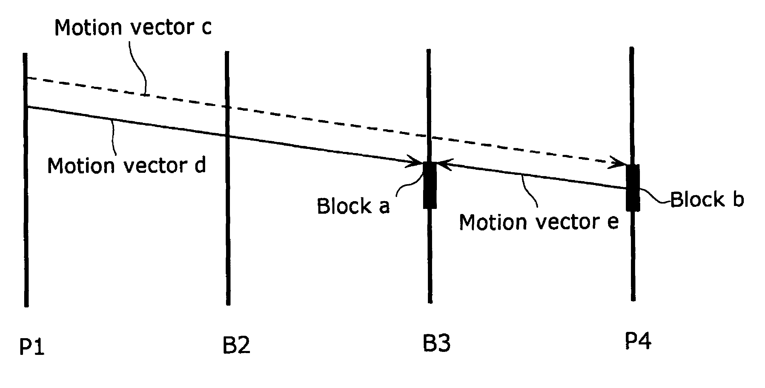
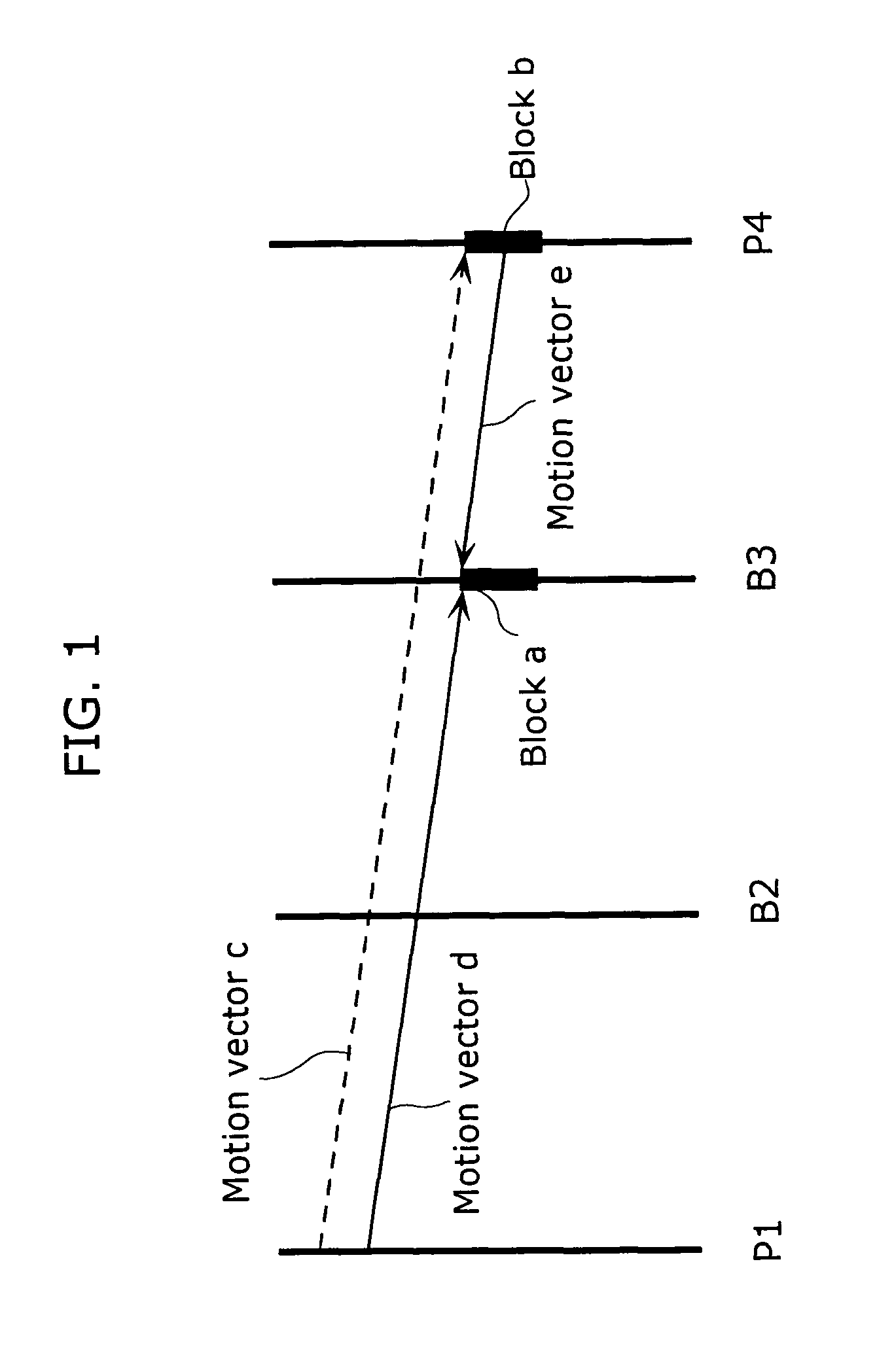
[0032]In order to solve the above-mentioned problem, the moving picture decoding method according to the present invention is a moving picture decoding method for decoding a moving picture with motion compensation using a motion vector, the moving picture being a sequence of pictures, each of which is made up of a plurality of blocks, the method including: a step of inputting a bit stream containing limitation information indicating a limitation on storage of at least one motion vector used in motion compensation of a current block to be decoded; a step of extracting the limitation information after decoding the bit stream; and a step of storing said at least one motion vector into a storage area based on the limitation information. As a result, it is possible to limit the storage of motion vector used in performing motion compensation on a current block to be coded within a picture containing a plurality of blocks.
[0039]As mentioned above, according to the moving picture coding method and the moving picture decoding method in the present invention, it is possible to generate a bit stream with a higher coding efficiency, while reducing the memory size for storing motion vectors necessary for coding in direct mode. Thus the practical value of the present invention is high.

Problems solved by technology

As a result, it is possible to show a limitation on the storage of motion vector used in performing motion compensation on a current block to be coded within a picture containing a plurality of blocks.

Method used


Image

  • Moving picture encoding method, moving picture decoding method, and recording medium
  • Moving picture encoding method, moving picture decoding method, and recording medium
  • Moving picture encoding method, moving picture decoding method, and recording medium

Examples


first embodiment

[0082]FIG. 5 is a block diagram showing the configuration of a moving picture coding apparatus 100 in the first embodiment of the present invention. The moving picture coding apparatus 100 is a moving picture coding apparatus that, during the coding of each picture, only stores in memory the motion vectors estimated from a reference picture coded immediately before a current picture to be coded and, when during the coding of a B-picture in direct mode, the vector to be referred is not stored within the memory, codes using a different method from an existing direct mode. The apparatus includes a frame memory 101, a difference calculation unit 102, a prediction error coding unit 103, a bit stream generation unit 104, a prediction error decoding unit 105, an addition unit 106, a frame memory 107, a motion vector estimation unit 108, a mode selection unit 109, a coding control unit 110, switches 111 to 115, and a motion vector storage unit 116. The frame memory 101 is a picture memory f...

second embodiment

[0128]A moving picture decoding apparatus 700 in the second embodiment of the present invention will be explained with reference to FIG. 11. FIG. 11 is a block diagram showing the configuration of the moving picture decoding apparatus 700 in the second embodiment. The moving picture decoding apparatus 700 is a moving picture decoding apparatus that stores the motion vectors of reference pictures into the memory according to the motion vector storage method described as header information within a bit stream, and decodes current pictures for decoding. It includes a bit stream analysis unit 701, a prediction error decoding unit 702, a mode decoding unit 703, a motion compensation decoding unit 705, a motion vector storage unit 706, a frame memory 707, an addition unit 708, a switch 709 and a switch 710.

[0129]FIG. 12A is a diagram showing the sequence of pictures included within a bit stream. FIG. 12B is a diagram showing the sequence of the pictures shown in FIG. 12A, when reordered i...

third embodiment

[0161]In the aforementioned first embodiment, the case where the information regarding the storage size of motion vectors is described in a header within a bit stream is discussed. However, the description of such information should not be limited to the header within a bit stream. For example, such information may be described in the management information, not included within a bit stream. Hereinafter, the moving picture coding apparatus, as well as the recording apparatus in the third embodiment of this present invention shall be explained, with reference to FIG. 13 to FIG. 17. FIG. 13 is a block diagram showing the outline configuration of a recording apparatus 500, for recording onto a recording medium such as DVD, the management information for managing the reproduction of data from the recording medium and coded Audio Visual (AV) data. The recording apparatus 500 is a recording apparatus that codes and records video data accompanied by sound onto a recording medium, and inclu...


PUM


Abstract

In coding a picture to be used as a reference picture by another picture, a motion vector used in inter picture predictive coding is stored into the motion vector storage unit (116). However, the storage of a motion vector is controlled by the coding control unit (110) in such a way that motion vectors of pictures, fewer in number than the number of reference pictures, are stored into the storage unit (116). In the case where direct mode is used in coding a B-picture, if the motion vector to be referred to in coding in direct mode is stored in the motion vector storage unit (116), coding is performed using such motion vector. Further, in the case where the motion vector is not stored in the storage unit (116), coding is performed with the motion vector as “0”, and using a motion vector of a neighboring block.

Description

TECHNICAL FIELD[0001]The present invention relates to a picture coding method for the efficient compression of moving pictures and a picture decoding method for correctly decoding the compressed moving pictures, and particularly to a picture coding method and picture decoding method using direct mode for processing.BACKGROUND ART[0002]In the age of multimedia which integrally handles audio, video and other information, existing information media, i.e., newspaper, magazine, television, radio, telephone and other means through which information is conveyed to people, have recently come to be included in the scope of multimedia. Generally, multimedia refers to something that is represented by associating not only characters, but also graphics, sound, and especially images, and the like, together, but in order to include the aforementioned existing information media in the scope of multimedia, it becomes a prerequisite to represent such information in digital form.[0003]However, if we a...

Claims


Application Information

Patent Timeline
IPC IPC(8): H04N7/12H04N11/02H04N11/04H04N7/26H04N7/32H04N7/36H04N7/46
CPCH04N19/70H04N19/513H04N19/426H04N19/573H04N19/577
Inventor KONDO, SATOSHIKADONO, SHINYAHAGAI, MAKOTOABE, KIYOFUMI
Owner PANASONIC CORP
Learn More