Banded graph cut segmentation algorithms with laplacian pyramids

a laplacian pyramid and graph cutting technology, applied in the field of multi-level image segmentation, to achieve the effect of accurate segmentation, thin structure, and light additional computational burden

Active Publication Date: 2010-10-26
IP3 2022 SERIES 922 OF ALLIED SECURITY TRUST I
View PDF2 Cites 11 Cited by
  • Summary
  • Abstract
  • Description
  • Claims
  • Application Information

AI Technical Summary

Benefits of technology

[0009]More particularly, a heuristic referred to as Banded Graph Cuts (BGC) has recently been introduced for producing fast, low-memory approximations to graph cuts, see a paper by H. Lombaert, Y Sun, L. Grady and C. Xu, entitled “A multilevel banded graph cuts method for fast image segmentation”, published in Proceedings of ICCV 2005, volume I, pages 259-265, Beijing, China, 2005, IEEE 1.23 and published U.S. Patent Application Pub. No. 2006 / 015934 A1, published Jul. 20, 2006, application Ser. No. 11 / 313,102 filed Dec. 20, 2005, entitled “Multilevel Image Segmentation”, inventors Yiyong Sun, Herve Lombaert, Leo Grady and Chenyang Xu, assigned to the same assignee as the present patent application, the entire subject matter thereof being incorporated herein by reference. The BGC method produces fast, low-memory approximations to graph cuts wherein a hierarchical image pyramid is constructed by repetitively downsampling (i.e., reduced resolution or coarsening of) the original, highest resolution image a specified number of times. Foreground (i.e., object of interest) and background seeds on the original high-resolution image are also downsampled. In the smallest image (the one width the least resolution and hence fewest pixels), a full graph cut algorithm is run, and the resulting segmentation is iteratively propagated toward the fine-level resolution using any number of standard, well-known methods. In general, each pixel of the coarse-level image is identified with several pixels on the fine-level image which are all given the same segmentation label as the associated coarse-level pixel. Since the segmentation is performed with the fewest number pixels, the computation time is reduced compared to segmentation with the original highest-resolution image. For each level of downsampling, the boundary of the segmentation is projected onto the next, fine-resolution, level while being dilated (i.e., the original boundary is converted to a “band”) by a specified amount d to create a band around the object. The graph cut algorithm is then run for this sparse (i.e., downsampled) graph. Hence, a tradeoff between the memory / time requirements and segmentation accuracy (i.e., inaccuracies resulting from the processing of downscaled data) is introduced through specification of the maximum pyramid level (i.e., the number of downscalings) and dilation size. Although this heuristic greatly reduces the memory and time consumption, in some applications it is desirable to detect thin structures (i.e., objects) such as vessels in medical imaging data.
[0011]The BGC algorithm is not the only approach to increasing the computational efficiency of Graph Cuts. The Lazy Snapping algorithm described in a paper by Li, Y. et. al. “Proceedings of ACM SIGGRAPH 2004 (2004) 303-308 performs a pre-segmentation grouping of the pixels using a watershed transform described by Roerdink et al., “The watershed transformation: Definitions, algorithms, and parallelization strategies”, Fund. Information 41 (2002) 187-228 and treats each watershed basin as a supernode. Graph Cuts is then run on the graph of supernodes. By drastically reducing the number of nodes in the graph, this approach greatly increases the speed of Graph Cuts in practice. However, the computational savings are more difficult to predict with this approach since the number of supernodes is highly image dependent. Additionally, the authors of this approach offer no characterization of when to expect this coarsening approach to succeed or fail to produce the same cut given by full-resolution Graph Cuts.
[0013]The invention is an improvement in the BGC algorithm that preserves its computational advantages, but produces segmentations much closer to Graph Cuts when the segmentation target contains thin structures. This modification is based upon the use of a difference image when coarsening to identify thin structures that may be included into the band during the segmentation. The modification of the BGC algorithm allows for the accurate segmentation (relative to full-resolution Graph Cuts) of thin objects while preserving the computational advantages of BGC. The modification is born of the observation that thin structures are lost as a result of the coarsening operation involved in BGC. The invention uses a Laplacian pyramid to recover this lost information and extend the band such that high-threshold pixels are included. In this manner, the additional computational burden is slight but thin structures are recovered. The extra computational burden comes only from considering a small number of additional pixels in the band and by computation of the Laplacian pyramid, which need not be computed explicitly and therefore requires simply an additional linear-time pass over the image.

Problems solved by technology

Processing these images places a large computational burden on the various devices that perform image processing.
More particularly, the Graph Cuts method performs at interactive speeds for smaller images / volumes, but an unacceptable amount of computation time is required for the large images / volumes common in medical applications.
However, for high-resolution images or medical volumes, the computational burden is still too large for the algorithm to operate at an interactive speed.
However, the computational savings are more difficult to predict with this approach since the number of supernodes is highly image dependent.
Additionally, the authors of this approach offer no characterization of when to expect this coarsening approach to succeed or fail to produce the same cut given by full-resolution Graph Cuts.
The extra computational burden comes only from considering a small number of additional pixels in the band and by computation of the Laplacian pyramid, which need not be computed explicitly and therefore requires simply an additional linear-time pass over the image.
1) Obtaining a high-resolution (i.e., original or master) image, of an object of interest disposed in background.
2) Using an outside process (e.g., a user) to partial label the image with some pixels being labeled “object”, other pixels being labeled “background” and still others (most) being unlabeled. This initial partial labeling is referred to as “seeds”.
3) Downsampling (i.e., coarsening or reducing in resolution) the partially labeled high-resolution image, both the image intensities and the partial labeling, to a coarse version of both.
4) Performing a “Graph Cuts” algorithm on the coarsen image to convert this partial labeling on the coarse image into a full labeling of the coarse image. That is, the “Graph Cuts” algorithm inputs the partial labeling and produces a full labeling. That is, the “Graph Cuts” algorithm results in previously unlabeled pixels being labeled as either background or object.
5) Generating from the coarse labeling and coarse image, a new, fine-level (high-resolution) image with all pixels being labeled. However, due to the information lost in the coarsening process, and there is uncertainty about this labeling. So, the process converts this full labeling to a partial labeling in order to reflect this uncertainty by the following process:A) Any pixels near the point where the labels is switch from object to background (i.e., the boundary) become unlabeled (this is referred to as the “banded” part)B) A comparison is made between the pixels in the new fine-level image to the corresponding pixels in the original (master) image and anywhere there is a significant discrepancy in the intensity between two corresponding pixels, the labeling associated with the pixel is changed to “unlabeled”. The result is a partially labeled image of high-resolution.
6) The process runs the Graph Cuts algorithm here to produce a fully labeled, high-resolution image.

Method used


Image

  • Banded graph cut segmentation algorithms with laplacian pyramids
  • Banded graph cut segmentation algorithms with laplacian pyramids
  • Banded graph cut segmentation algorithms with laplacian pyramids

Examples


Embodiment Construction

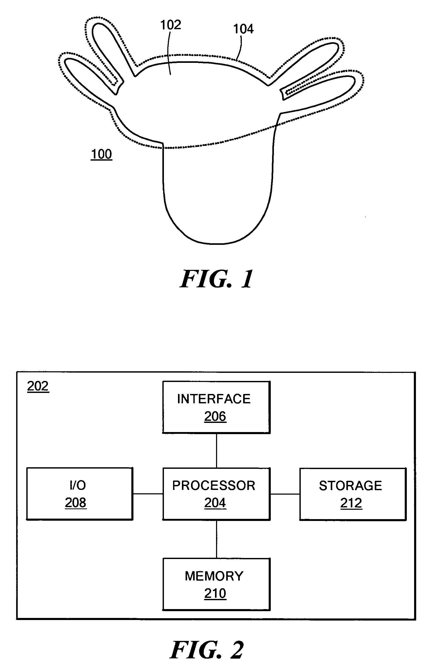
[0032]The following description describes the present invention in terms of the processing steps required to implement an embodiment of the invention. These steps may be performed by an appropriately programmed computer, the configuration of which is well known in the art. An appropriate computer may be implemented, for example, using well known computer processors, memory units, storage devices, computer software, and other components. A high level block diagram of such a computer is shown in FIG. 2. Computer 202 contains a processor 204 which controls the overall operation of computer 202 by executing computer program instructions which define such operation. The computer program instructions may be stored in a storage device 212 (e.g., magnetic disk, optical disk, or any other computer readable medium) and loaded into memory 210 when execution of the computer program instructions is desired. Memory 210 may also be used to store data used during the various steps of the method. Co...


PUM


Abstract

A process for segmenting an object of interest from background, comprising: obtaining a master, high-resolution image of an object disposed within a background; applying a first band graph cut process to the master image generating a second image with the object being segmented from the background to a first approximation; and, comparing the second image with the master image to produce a comparison image with pixels identified by the comparison to be background images being removed from the comparison image.

Description

CROSS REFERENCE TO RELATED APPLICATION[0001]This application claims priority from U.S. Provisional application No. 60 / 759,415 filed Jan. 17, 2006, which is incorporated herein by reference.TECHNICAL FIELD[0002]This invention relates generally to image processing, and more particularly to multilevel image segmentation.BACKGROUND AND SUMMARY[0003]As is known in the art, digital image processing is becoming increasingly popular as digital imaging devices continue to become more powerful. For example, digital cameras can generate pictures having 10 million pixels, and Computed Tomography (CT) scanners may produce volume data having more than 100 million voxels. Processing these images places a large computational burden on the various devices that perform image processing.[0004]One type of processing that is often performed on image data is segmentation, whereby a boundary is determined between different portions of the image. For example, in digital photography, it is often desirable t...

Claims


Application Information

Patent Timeline
Patent Type & Authority Patents(United States)
IPC IPC(8): G06K9/00G06K9/34
CPCG06K9/342G06K9/6224G06T7/0081G06T7/0093G06T2207/20016G06T2207/20072G06T2207/20101G06T2207/20144G06T7/11G06T7/162G06T7/194G06V10/267G06V10/7635G06F18/2323
Inventor SINOP, ALI KEMALGRADY, LEO
Owner IP3 2022 SERIES 922 OF ALLIED SECURITY TRUST I
Why Eureka
Try Eureka