Tubular threaded joint

a technology of threaded joints and threaded joints, which is applied in the direction of screw threaded joints, hose connections, mechanical equipment, etc., can solve the problems of inability to withstand a large compressive load, leakage, and increase the development of wells in disadvantageous environments such as in the sea or in the polar regions, so as to reduce the tightening force at the time of tightening the threaded joint, the effect of easy tightening operation

Active Publication Date: 2010-11-02
VALLOUREC OIL & GAS FRANCE SAS +1
View PDF20 Cites 22 Cited by
  • Summary
  • Abstract
  • Description
  • Claims
  • Application Information

AI Technical Summary

Benefits of technology

[0024]It is an object of the present invention to provide a tubular threaded joint which has excellent resistance to compression and which facilitates connection of pipes in the field while in a vertical state.
[0026]In the tubular threaded joint proposed in above-described WO 2004 / 109173, an improvement in resistance to compression is achieved by modifying the portion closer to the end of the pin than the metal-to-metal seal surface. Upon repeated investigations on the basis of that tubular threaded joint, the present inventors found that if the shape of a thread, and particularly the stabbing flank clearance, which is the clearance in the pipe axial direction between the stabbing flanks of the male screw thread of the pin and the female screw thread of the box, and the length of the lip zone satisfy a certain relationship, plastic deformation of the lip zone due to compression is prevented from occurring, and the resistance to compression of a tubular threaded joint is further improved.
[0045]According to the present invention, by extending the length of the lip zone, which is the distance in the member having a contacting end shoulder surface of a tubular threaded joint between the engaged threaded zone and the end shoulder surface, to at least 140 times and preferably at least 160 times the stabbing flank clearance of the male and female threads, resistance to compression is effectively conferred by the stabbing flanks of the threads (or by the remaining effective or engaged portions of the stabbing flanks when the upper portion of the stabbing flank of the pin or the box has been removed by chamfering or beveling), and the resistance to compression of a tubular threaded joint is increased.
[0046]By controlling the stabbing flank clearance to be within a certain range, variations in the tightening force at the time of tightening the threaded joint can be decreased. In addition, by suitably designing the shape of the threads and particularly the direction of the crest and the root, the shape of a stabbing flank and is the shape of the chamfer on the stabbing flank side, problems and misengagement of threads due to deviation of the insertion angle at the time of restricted tightening operation such as tightening operation in the field in a vertical state which is being increasingly automated can be decreased, thereby making such a tightening operation easy.

Problems solved by technology

However, in recent years, as the environments for excavation and production of crude oil and natural gas become severe, high-performance special threaded joints referred to as premium joints are being increasingly used.
Accordingly, if the thickness of the shoulder surfaces is not large (or if the stiffness of the shoulder surfaces is not high), they cannot withstand a large compressive load.
However, in recent years, the depth of wells has been increasing, sloping wells and horizontal wells in which the well bore bends underground are increasing, and the development of wells in disadvantageous environments such as in the sea or in polar regions is increasing.
If the external pressure becomes high, a gap may develop between the seal surfaces, leading to the occurrence of leakage, e.g., a situation in which external fluid penetrates into the interior of the pipe body through the gap.
Therefore, if a compressive load corresponding to 40-60% of the yield strength of the pipe body is applied, with most premium joints, the lip zone of the pin undergoes a substantial plastic deformation, leading to a marked decrease in the sealing performance of the seal surface adjacent to this portion.
However, if the amount of swaging is too great, with casing, there are cases in which a pipe which is inserted into its interior catches on the swaged portion, and with tubing, there are cases in which turbulence develops in a fluid such as crude oil flowing inside the tubing due to the swaged portion and causes erosion.

Method used


Image

  • Tubular threaded joint
  • Tubular threaded joint
  • Tubular threaded joint

Examples


example 1

[0096]In order to clearly demonstrate the effects of the present invention, a compressive load was applied to the test members shown in Table 1 by tightening, and deformation of the lip zone was observed.

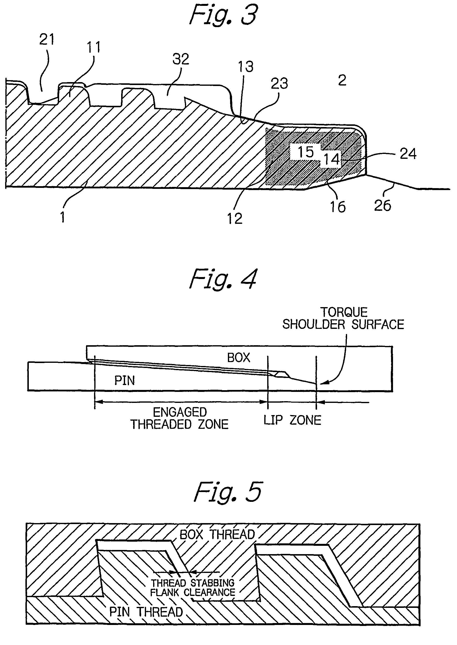
[0097]Each of the test members shown in Table 1 was a threaded joint for oil country tubular goods of the coupling type like that shown in FIG. 3. They were for use with respect to a 9.625″×53.5 (lb / ft) steel pipe (outer diameter of 244.5 mm and wall thickness of 13.84 mm). The steel used for all of the test members was that specified by API specification P110. The shoulder surfaces were an end shoulder surface located at the end of the pin and a corresponding shoulder surface of the box. The lip zone had on its outer periphery a metal-to-metal seal surface (length of 5.5 mm) in the vicinity of the threaded zone and a noncontacting region on the outer end side thereof. In contrast to FIG. 3, there was no unengaged thread on the end portion of the threaded zone.

[0098]The screw thread...

example 2

[0102]An evaluation test was carried out in the same manner as in Example 1, but in this example, the stabbing flank of the male thread of the pin was divided into a first portion on the root side and a second portion on the crest side having different slope angles. In this example, in order to simplify analysis, as shown in FIGS. 6 and 8, the first portion and the second portion of the stabbing flanks were both made conical surfaces (namely, having a longitudinal section along the pipe axis substantially formed by a straight line). The angle of slope of the stabbing flank was 10° for the first portion and 45° for the second portion. The ratio of the lip length to the stabbing flank clearance was 200 (the stabbing flank clearance was 0.1 mm and the lip length was 20 mm). By varying the height of the first portion of the stabbing flank, the ratio of the height of the first portion with respect to the overall thread height (the thread stabbing flank height ratio in Table 2) was varied...


PUM


Abstract

A tubular threaded joint which has excellent resistance to compression and which permits easy tightening operation in the field in a vertical state comprises a pin having a male threaded zone and a box having a female threaded zone. The pin or the box has an end shoulder surface on its end, and the other member has a shoulder surface which abuts against the end shoulder surface. The screw threads of the male threaded zone and the female threaded zone are trapezoidal threads having a crest, a load flank, and a stabbing flank. The lip length, which is the distance in the axial direction of a member having an end shoulder surface between the end shoulder surface and the closest engaged thread to that surface, is at least 140 times the stabbing flank clearance, which is the distance in the axial direction between the stabbing flanks of the male thread and the female thread when the load flanks of the male and female threads contact each other. The stabbing flank of the male thread is preferably chamfered.

Description

[0001]This application is a Continuation of International Patent Application No. PCT / JP2007 / 057516, filed Mar. 28, 2007, and was published in English.TECHNICAL FIELD[0002]This invention relates to a tubular threaded joint suitable for use in connecting steel pipes such as oil country tubular goods (OCTG), riser pipes, and line pipes. More particularly, it relates to a tubular threaded joint which has excellent resistance to compression and which makes it easy to connect steel pipes in a vertical state in the field.BACKGROUND ART[0003]Steel pipes such as OCTG (oil country tubular goods including oil well tubing, casing, and drill pipes) used for the exploration and production of oil wells and gas wells, as well as riser pipes, line pipes, and the like are usually connected by a tubular threaded joint.[0004]A tubular threaded joint is constituted by a pin, which is a male threaded element provided on an end portion of a first tubular member, and a box, which is a female threaded eleme...

Claims


Application Information

Patent Timeline
Patent Type & Authority Patents(United States)
IPC IPC(8): F16L25/00
CPCF16L15/004E21B17/042F16L15/06
Inventor HAMAMOTO, TAKAHIROSUMITANI, KATSUTOSHISUGINO, MASAAKIIWAMOTO, MICHIHIKOYAMAMOTO, MIYUKICHARVET-QUEMIN, JEAN-FRANCOISLE CHEVALIER, BENOITVERGER, ERIC
Owner VALLOUREC OIL & GAS FRANCE SAS
Why Eureka
Try Eureka