
Junction box for photovoltaic modules

a junction box and photovoltaic module technology, applied in the direction of electrical apparatus casings/cabinets/drawers, coupling device connections, hermetically sealed casings, etc., can solve the problems of increasing difficulty, time, and/or cost of connecting the junction box to the pv modul

Inactive Publication Date: 2010-11-02
TE CONNECTIVITY CORP
View PDF12 Cites 144 Cited by
  • Summary
  • Abstract
  • Description
  • Claims
  • Application Information

AI Technical Summary

Problems solved by technology

Bending the foil through the opening of the dielectric substrate and wrapping the foil around the electrical contacts within the housing may increase a difficulty, a time, and / or a cost of connecting the junction box to the PV module.

Method used


Image

  • Junction box for photovoltaic modules
  • Junction box for photovoltaic modules
  • Junction box for photovoltaic modules

Examples


Embodiment Construction

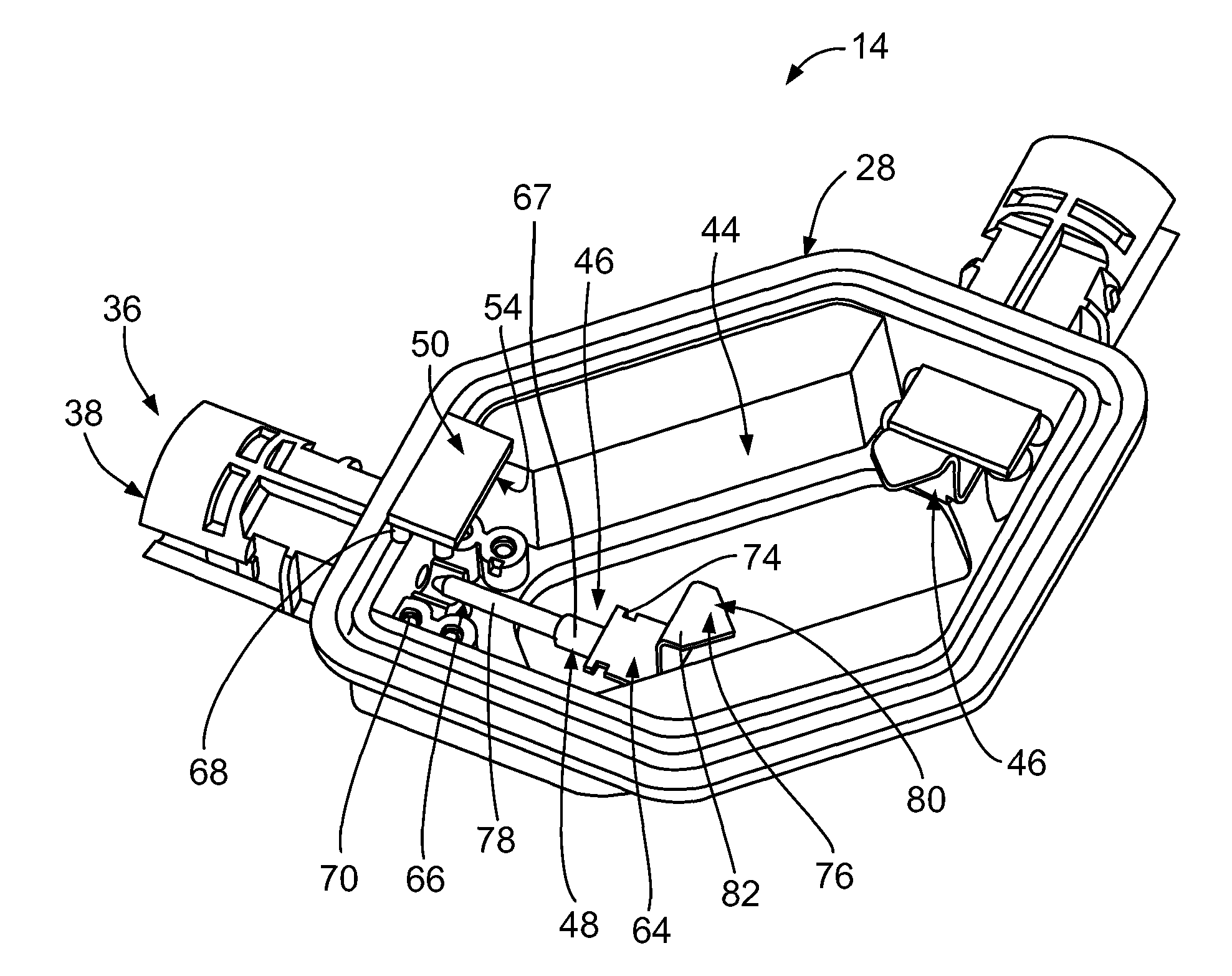
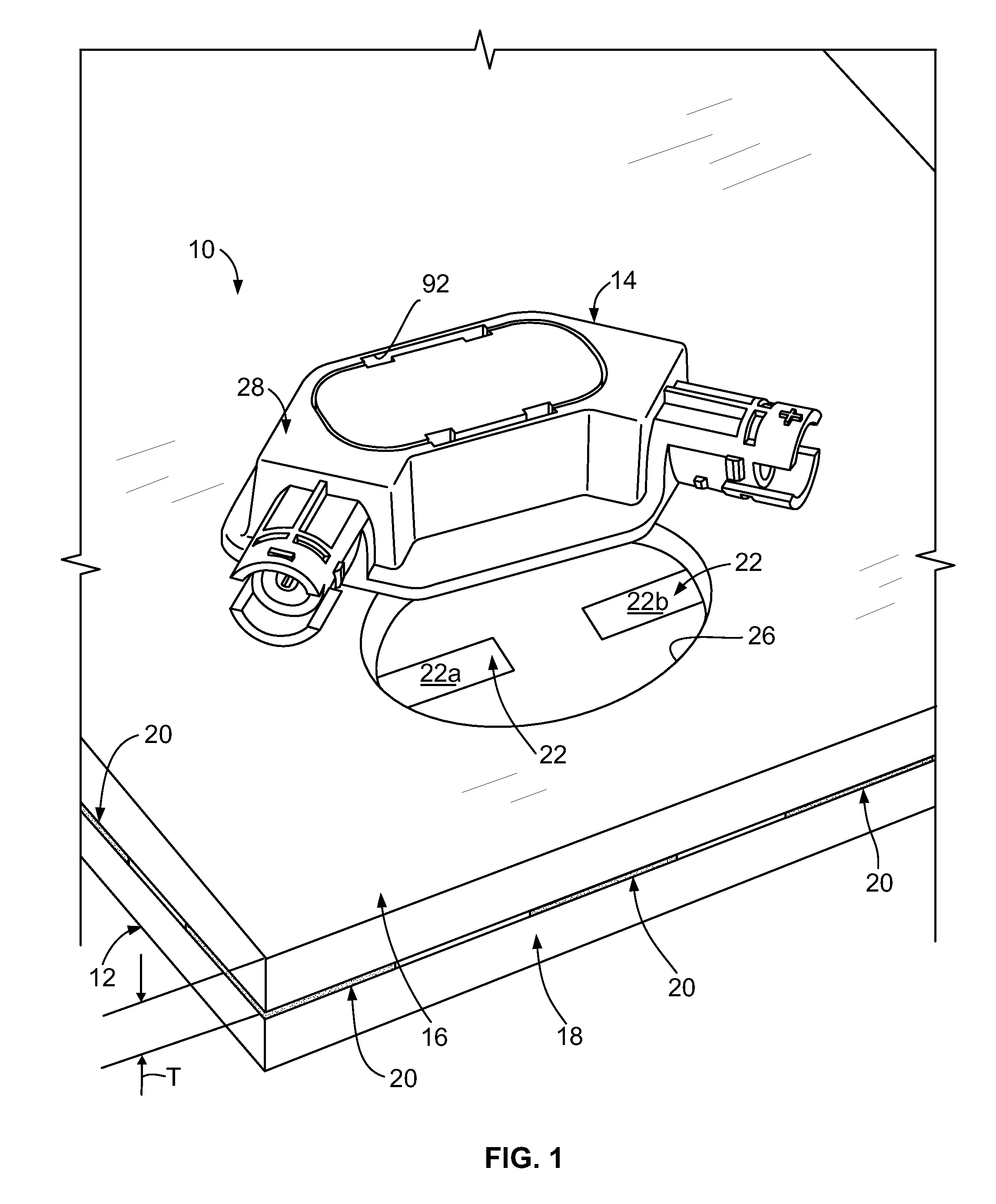
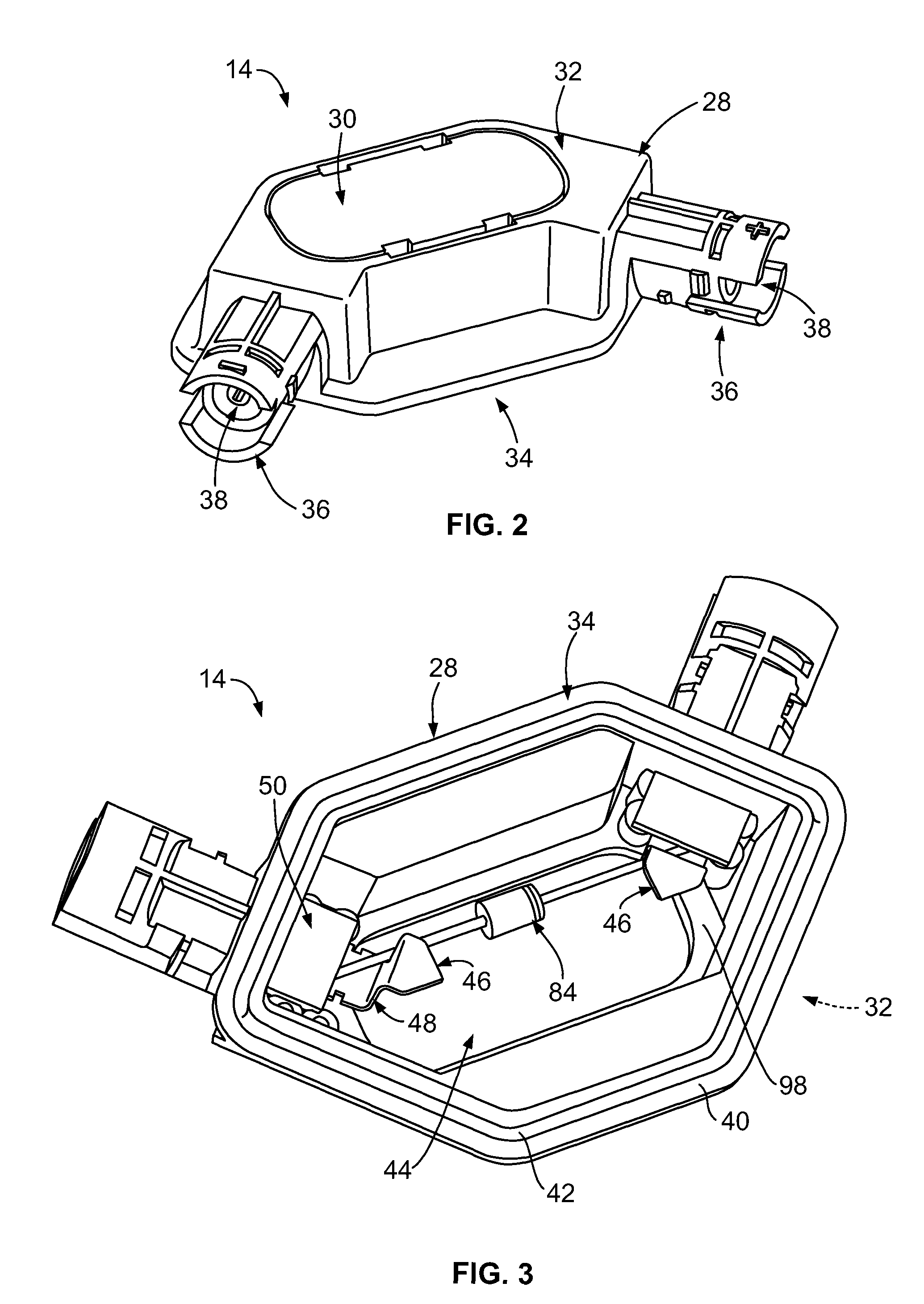
[0016]FIG. 1 is a partially exploded perspective view of an exemplary embodiment of a junction box and photovoltaic (PV) module assembly 10. The assembly 10 includes a PV module 12 and a junction box 14. Only a portion of the PV module 12 is shown herein. The PV module 12 includes a dielectric substrate 16, a transparent panel 18, and a plurality of PV cells 20 held between the dielectric substrate 16 and the transparent panel 18. When irradiated by a light source (such as, but not limited to, sunlight and / or the like), the PV cells 20 convert the energy of photons into electrical power. Each PV cell 20 may be any type of PV cell 20, such as, but not limited to, a thin film PV cell and / or the like. The PV cells 20 of the PV module 12 are electrically interconnected with each other, in series and / or parallel, by an electrically conductive foil 22, such as, but not limited to, a metallic foil and / or the like. The foil 22 of the PV module is exposed through an opening 26 within the die...


PUM


Abstract

A junction box is provided for electrically connecting a photovoltaic (PV) module to a power distribution system having a mating connector. The junction box includes a housing having a mounting side configured to be mounted on the PV module. The housing includes a mating interface and an opening extending into the housing through the mounting side. The housing is configured to mate with the mating connector of the power distribution system at the mating interface. An electrical contact is held by the housing. The electrical contact includes an integrally formed, one-piece body. The body of the electrical contact includes a base, a mating end extending from the base, and a PV module end extending from the base. The base of the body of the electrical contact is held within the opening of the housing such that the mating end extends along the mating interface for engagement with the mating connector. The PV module end of the body extends outwardly from the opening on the mounting side of the housing for engagement with foil of the PV module.

Description

BACKGROUND OF THE INVENTION[0001]The subject matter described and / or illustrated herein relates generally to photovoltaic (PV) modules, and, more particularly, to a junction box for interconnecting PV modules with a power distribution system.[0002]To produce electricity from solar energy, PV modules include a plurality of PV cells interconnected in series and / or parallel, according to the desired voltage and current parameters. PV cells are essentially large-area semiconductor diodes. Due to the photovoltaic effect, the energy of photons is converted into electrical power within a PV cell when the PV cell is irradiated by a light source, such as sunlight. Within a PV module, the PV cells are typically sandwiched between a transparent panel and a dielectric substrate. The PV cells within the PV module are typically interconnected by an electrically conductive foil, such as a metallic foil. A plurality of PV modules that are mechanically and electrically connected together is sometime...

Claims


Application Information

Patent Timeline
Patent Type & Authority Patents(United States)
IPC IPC(8): H01R13/00
CPCH02S40/34Y02E10/50
Inventor LAUERMANN, MARK EDWINSTAHL, DANIEL EUGENE
Owner TE CONNECTIVITY CORP
Learn More