Active material and light emitting device

a technology of active materials and light emitting devices, which is applied in the direction of gas purification by liquid washing, point-like light sources, combustion air/fuel air treatment, etc. it can solve the problems of dripping wax damage to furniture and skin, scented candles are not without drawbacks, and few things are quite as versatile at setting the ambience in an area as scented candles

Inactive Publication Date: 2010-11-02
SC JOHNSON & SON INC
View PDF536 Cites 148 Cited by
  • Summary
  • Abstract
  • Description
  • Claims
  • Application Information

AI Technical Summary

Problems solved by technology

Because of their wide array of shapes and sizes, as well as the seemingly limitless number of available scents, few things are quite as versatile at setting the ambience in an area as scented candles.
Scented candles are not without drawbacks, however.
For example, dripping wax can damage furniture and the skin and, in the extreme, an open flame can lead to a structure fire.
While these patents may suggest devices that mimic the visual aesthetics of a candle, they fail to provide the scented candle experience, i.e., they fail to emit fragrance in addition to light.
Although these representative devices provide fragrance emission, they do not provide the visual aesthetic of a candle.

Method used


Image

  • Active material and light emitting device
  • Active material and light emitting device
  • Active material and light emitting device

Examples


first embodiment

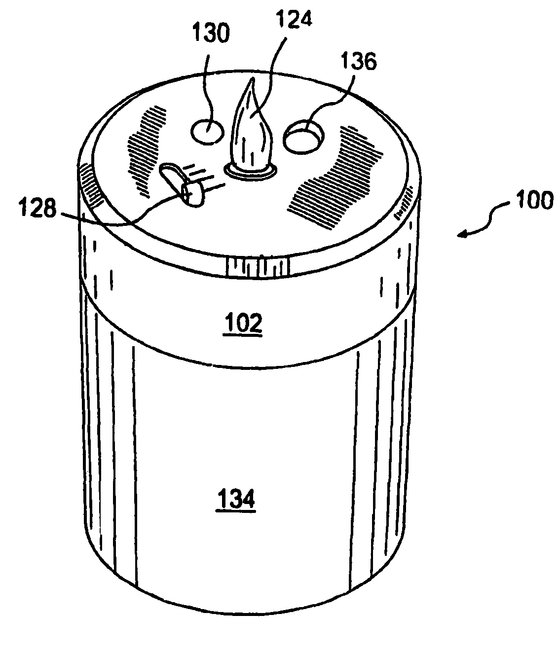
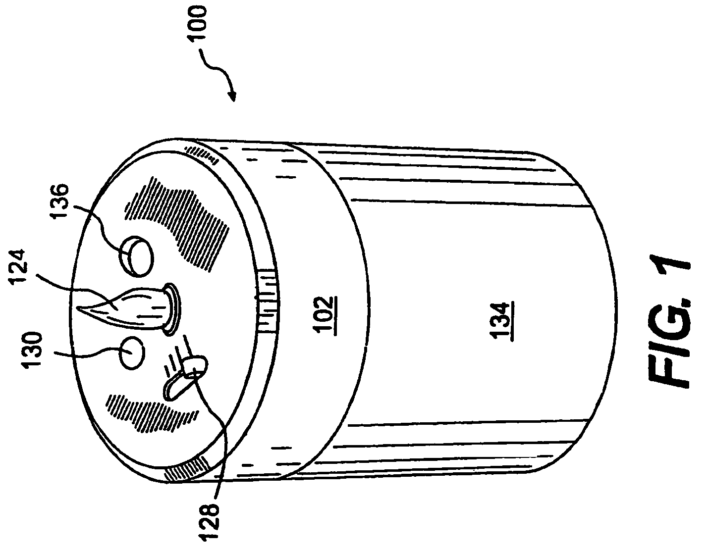
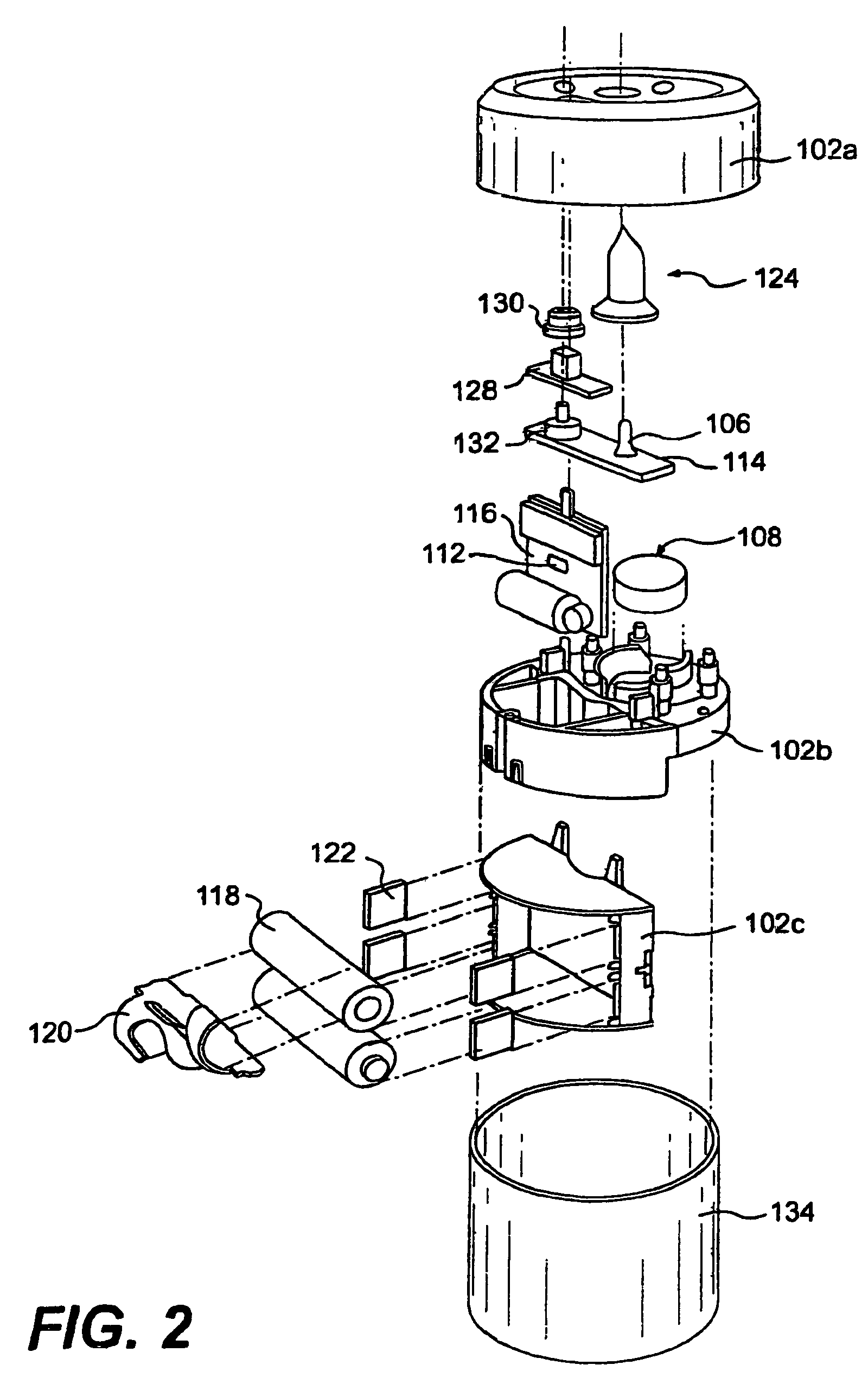
[0079]The first embodiment is depicted in FIGS. 1-5 and. As seen best in FIGS. 2 and 3 a chassis 102 is provided that comprises a chassis cover 102a, a chassis upper portion 102b, and a chassis lower portion 102c. Disposed on the chassis 102 are two batteries 118, a wick-based atomizer assembly 108, a single LED 106, and two printed circuit boards 114, 116. Each of two microcontrollers 110, 112 are disposed on the circuit boards 114, 116. As shown, the chassis cover 102a and the chassis upper portion 102b are joinable to form a cavity therebetween, and the chassis lower portion 102c depends downwardly from a bottom of the chassis upper portion 102b. In this embodiment, the atomizer assembly 108, the LED 106, the microcontrollers 110,112, and the printed circuit boards 114, 116 are disposed within the cavity formed between the chassis cover 102a and the chassis upper portion 102b. Electrical contacts 122, which the batteries 118 contact to supply the device 100 with power are dispose...

second embodiment

[0094]According to this second embodiment, a light and substance emitting device 200 is provided. Preferably, as mentioned above, the housing (i.e., the combined chassis 202 and base 234) of the device 200 is configured and sized to resemble a conventional pillar candle. As should be understood, since the LED 206 emitting the flickering light is disposed within the housing, much of the light will be transmitted through the sidewall of the base 234. Accordingly, at least a portion of the base 234 should be light transmissive. In addition, at least a portion of the chassis 202 may also be light transmissive. To these ends, all or a portion of the chassis 202 and / or the base 234 may be formed of one or more of glass, plastic, wax, and the like.

[0095]Variations of this second embodiment are also contemplated. For example, while the holder 234 is generally cylindrical, such is not required. Rectangular, square, and a myriad of other shapes and sizes are contemplated. In addition, while t...

third embodiment

[0096]A third embodiment will now be described with reference to FIGS. 8A-8C, 9, and 10. In this embodiment a light and active material emitting device 300 includes a chassis 302 comprising a chassis cover 302a and a chassis base 302b which together form a cavity that encases each of two LED's 306a, 306b, an active material emitter 308, two batteries 318, and a printed circuit board with microcontroller 310. The LED's 306a, 306b are connected either directly or indirectly to both of the batteries 318 and the microcontroller 310. In this embodiment, the LED's 306a, 306b are preferably located substantially centrally with respect to a top surface of the device, and above the active material emitter 308, the batteries 318, and the microcontroller 310, i.e., on a side of the active material emitter 308, the batteries 318, and the microcontroller 310 opposite to the chassis base 302b. At least a portion of the LED's 306a, 306b are preferably located above a top surface of the chassis cov...


PUM

PropertyMeasurementUnit
wavelength of emissionaaaaaaaaaa

Abstract

An active material and light emitting device comprises an ultrasonic atomizer assembly and a light emission device. The active material and light emitting device further includes a housing containing the atomizer assembly and the light emission device such that the atomizer assembly is disposed above the light emission device. The light emission device emits light that is transmitted through a medial portion of the housing.

Description

CROSS REFERENCE TO RELATED APPLICATIONS[0001]This application is a continuation-in-part of U.S. application Ser. No. 11 / 050,169, filed Feb. 3, 2005 now abandoned, entitled “Device Providing Coordinated Emission of Light and Volatile Active,” which claims the benefit of U.S. Provisional Application No. 60 / 541,067, filed Feb. 3, 2004 and also claims the benefit of a U.S. Provisional Application No. 60 / 723,166, filed on Oct. 3, 2005, entitled “Light Apparatus.”REFERENCE REGARDING FEDERALLY SPONSORED RESEARCH OR DEVELOPMENT[0002]Not applicableSEQUENTIAL LISTING[0003]Not applicableBACKGROUND OF THE INVENTION[0004]1. Field of the Invention[0005]The present invention relates to the integrated presentation of ambient conditions. More specifically, the present invention relates to the controlled and coordinated emission of light and an active material, into a given area, such as a room, from a single device.[0006]2. Description of the Background of the Invention[0007]Because of their wide ar...

Claims


Application Information

Patent Timeline
Patent Type & Authority Patents(United States)
IPC IPC(8): B05B17/06
CPCA01M1/205A61L9/037A61L9/122A61L9/127A61L9/14B05B17/0646B05B17/0684F21S10/04F21V3/04G02B6/0018A61L2209/12F21Y2101/02G02B6/0051F21Y2115/10G02B6/0001G02B6/00
Inventor MICHAELS, KENNETH W.HELF, THOMAS A.DUBIN, MATTHEW B.CRULL, JEFFREY L.FALENDYSZ, GREGORYWESTPHAL, NATHAN R.
Owner SC JOHNSON & SON INC
Why Eureka
Try Eureka