
Methods and apparatus for runway segmentation using sensor analysis

a sensor analysis and runway technology, applied in the direction of scene recognition, instruments, image enhancement, etc., can solve the problems of not being able to visually verify the correctness of navigation data and the svs database, the pilot may not be able to use navigation data to navigate the aircraft, and the actual data may not be accura

Active Publication Date: 2010-11-02
HONEYWELL INT INC
View PDF7 Cites 18 Cited by
  • Summary
  • Abstract
  • Description
  • Claims
  • Application Information

AI Technical Summary

Benefits of technology

The patent describes a system and method for identifying a runway with multiple corners using a camera and analysis module. The system generates a binary large object (BLOB) of the captured image and compares it to a template of the runway to determine if it represents a runway. The technical effect of this patent is to provide a reliable and accurate method for identifying runways, which can aid in various applications such as airport safety and security.

Problems solved by technology

However, under low visibility conditions the pilot may not be able to visually verify the correctness of navigation data and the SVS database.
Because SVS data is based on archived information (taken at earlier time than the time of the flight), the data can be impeded by updates into the scene, and thus, some cues may be missing from the actual data.
In addition, navigation data cannot be used to navigate the aircraft to avoid obstacles on or near a runway because SVS models do not provide real-time information related to obstacles.
Moreover, only a limited number of runways are equipped with adequate devices for providing accurate navigation attributes with the required accuracy to safely make low approaches and high-end equipment (e.g., ILS) is costly and is not available at all airports or to all runways at a particular airport.

Method used


Image

  • Methods and apparatus for runway segmentation using sensor analysis
  • Methods and apparatus for runway segmentation using sensor analysis
  • Methods and apparatus for runway segmentation using sensor analysis

Examples


Embodiment Construction

[0019]The following detailed description is merely exemplary in nature and is not intended to limit the invention, the application, and / or uses of the invention. Furthermore, there is no intention to be bound by any theory presented in the preceding background or the following detailed description.

[0020]An apparatus is provided for locating a runway by detecting the runway coordinates and edges within data representing a region of interest (ROI) provided by a synthetic vision sensor. The following aspects of the invention are described in conjunction with the pictorial illustrations and block diagrams, and those skilled in the art will appreciate that the scope of the invention is not limited to and / or by these illustrations. Modifications in the section, design, and / or arrangement of various components and steps discussed in what follows may be made without departing form the intended scope of the invention.

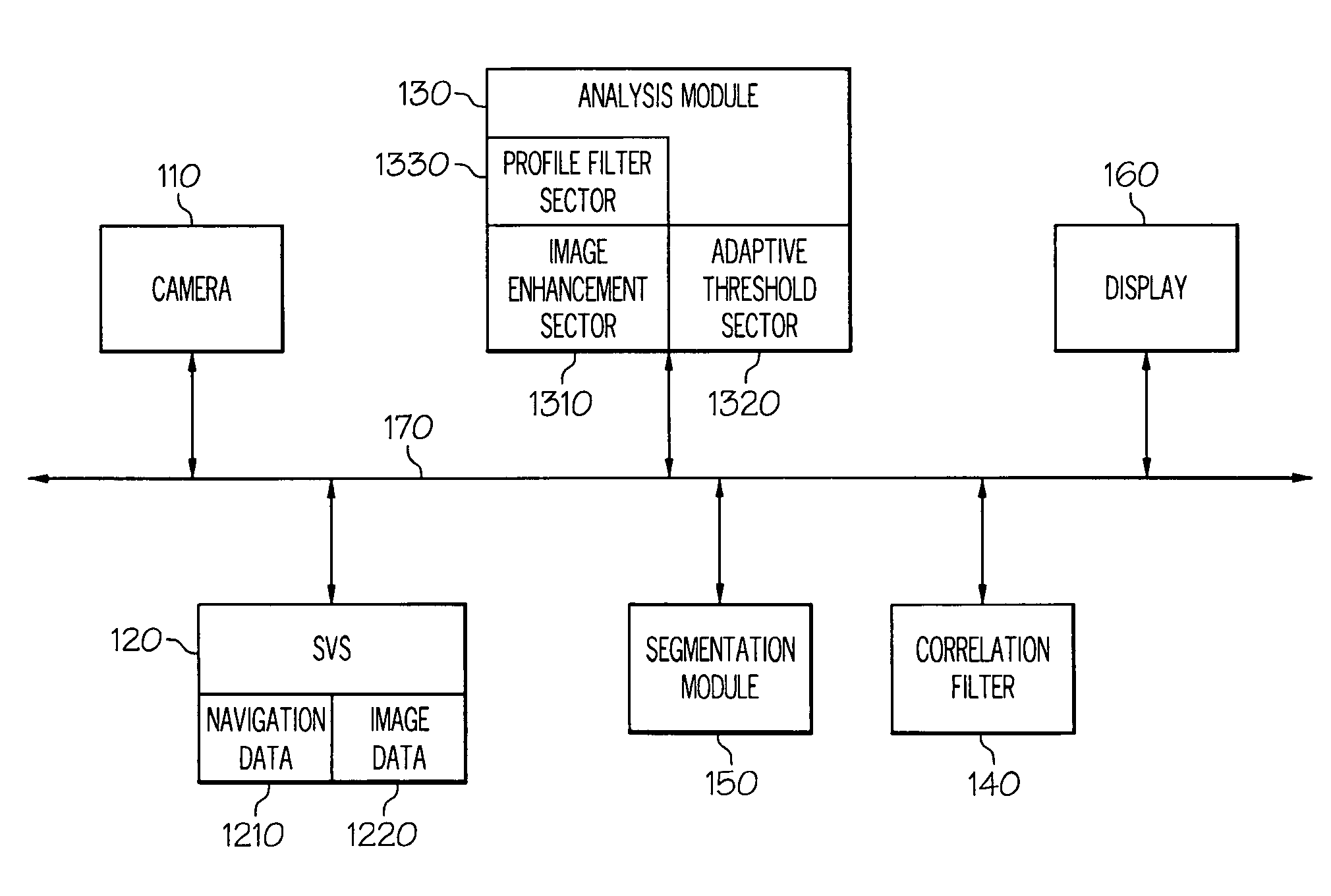
[0021]Turning now to the figures, FIG. 1 is a block diagram of one embodime...


PUM


Abstract

Systems and methods for determining whether a region of interest (ROI) includes a runway are provided. One system includes a camera for capturing an image of the ROI, an analysis module for generating a binary large object (BLOB) of at least a portion of the ROI, and a synthetic vision system including a template of the runway. The system further includes a segmentation module for determining if the ROI includes the runway based on a comparison of the template and the BLOB. One method includes the steps of identifying a position for each corner on the BLOB and forming a polygon on the BLOB based on the position of each corner. The method further includes the step of determining that the BLOB represents the runway based on a comparison of the polygon and a template of the runway. Also provided are computer-readable mediums storing instructions for performing the above method.

Description

CROSS-REFERENCES TO RELATED APPLICATIONS[0001]This application claims the benefit of U.S. Provisional Application No. 61 / 031,900, filed on Feb. 27, 2008.TECHNICAL FIELD[0002]The present invention relates generally to providing guidance to aircraft crew, and more particularly, relates to forming a combined sensor and synthetic navigation data that provides guidance to aircraft operators in limited or no visibility conditions.BACKGROUND[0003]The need to land aircraft, such as airplanes, helicopters, and spacecraft in zero / zero conditions is driving sensor fusion and computer vision systems for next-generation head-up displays. Safely landing the aircraft requires accurate information about the location of a target (e.g., runway). During an approach to a runway, the pilot must carefully control the navigation of the aircraft relative to a touchdown point. That is, pilots need to have a good situational awareness (e.g., heads up) of the outside world through heavy fog, smoke, snow, dust...

Claims


Application Information

Patent Timeline
Patent Type & Authority Patents(United States)
IPC IPC(8): G06K9/68G06G7/70G06V20/13
CPCG06T7/004G06T7/0081G06K9/0063G06T2207/10048G06T2207/30252G06T7/70G06T7/11G06V20/13
Inventor HAMZA, RIDA M.MOHIDEEN, MOHAMMED IBRAHIMRAMEGOWDA, DINESHFEYEREISEN, THEA L.
Owner HONEYWELL INT INC
Learn More