Apparatus and methods for producing multi-electrode cathode for X-ray tube

a multi-electrode cathode, x-ray tube technology, applied in the manufacture of electrode systems, x-ray tubes, electric discharge tubes/lamps, etc., can solve the problems of drop-in replacement, high heat damage to devices, and the formidable challenge of multi-electrode systems

Active Publication Date: 2010-11-09
GENERAL ELECTRIC CO
View PDF10 Cites 1 Cited by
  • Summary
  • Abstract
  • Description
  • Claims
  • Application Information

AI Technical Summary

Benefits of technology

[0009]The methods and apparatus detailed below describe a multi-electrode cathode for an X-ray tube and methods for producing the same that greatly simplify manufacturing while providing tight manufacturing tolerances for electrode placement.

Problems solved by technology

This high heat can damage the device unless mitigation techniques are utilized to reduce the heat before damage to the anode occurs.
Changes in either the location of the electrodes or the dimensions of the electrodes requires individual X-ray tube testing, calibration and focal spot control adjustment for each X-ray system produced which is time consuming, costly and prevent drop-in replacement should the X-ray tube need replacing.
The manufacture of such a multi-electrode system presents a formidable challenge because of the difficulty in placing and bonding the finished electrodes to tight manufacturing tolerances.

Method used


Image

  • Apparatus and methods for producing multi-electrode cathode for X-ray tube
  • Apparatus and methods for producing multi-electrode cathode for X-ray tube
  • Apparatus and methods for producing multi-electrode cathode for X-ray tube

Examples


Embodiment Construction

[0021]In the following detailed description of embodiments of apparatus and methods for producing multi-electrode cathode for X-ray tubes, reference is made to the accompanying drawings that form a part hereof, and in which is shown by way of illustration specific embodiments in which the invention may be practiced. These embodiments are described in sufficient detail to enable those skilled in the art to practice the embodiments, and it is to be understood that other embodiments may be utilized and that logical, mechanical, electrical and other changes may be made without departing from the scope of the embodiments. The following detailed description is, therefore, not to be taken in a limiting sense.

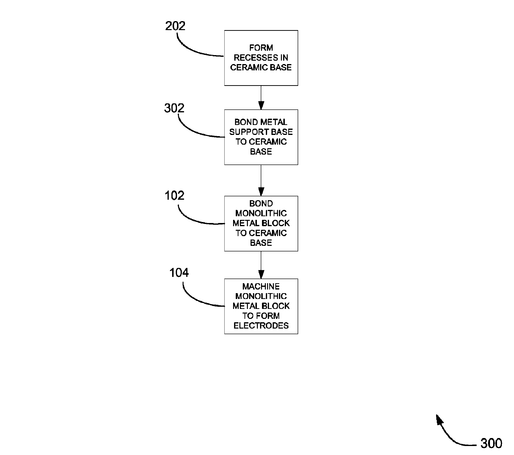
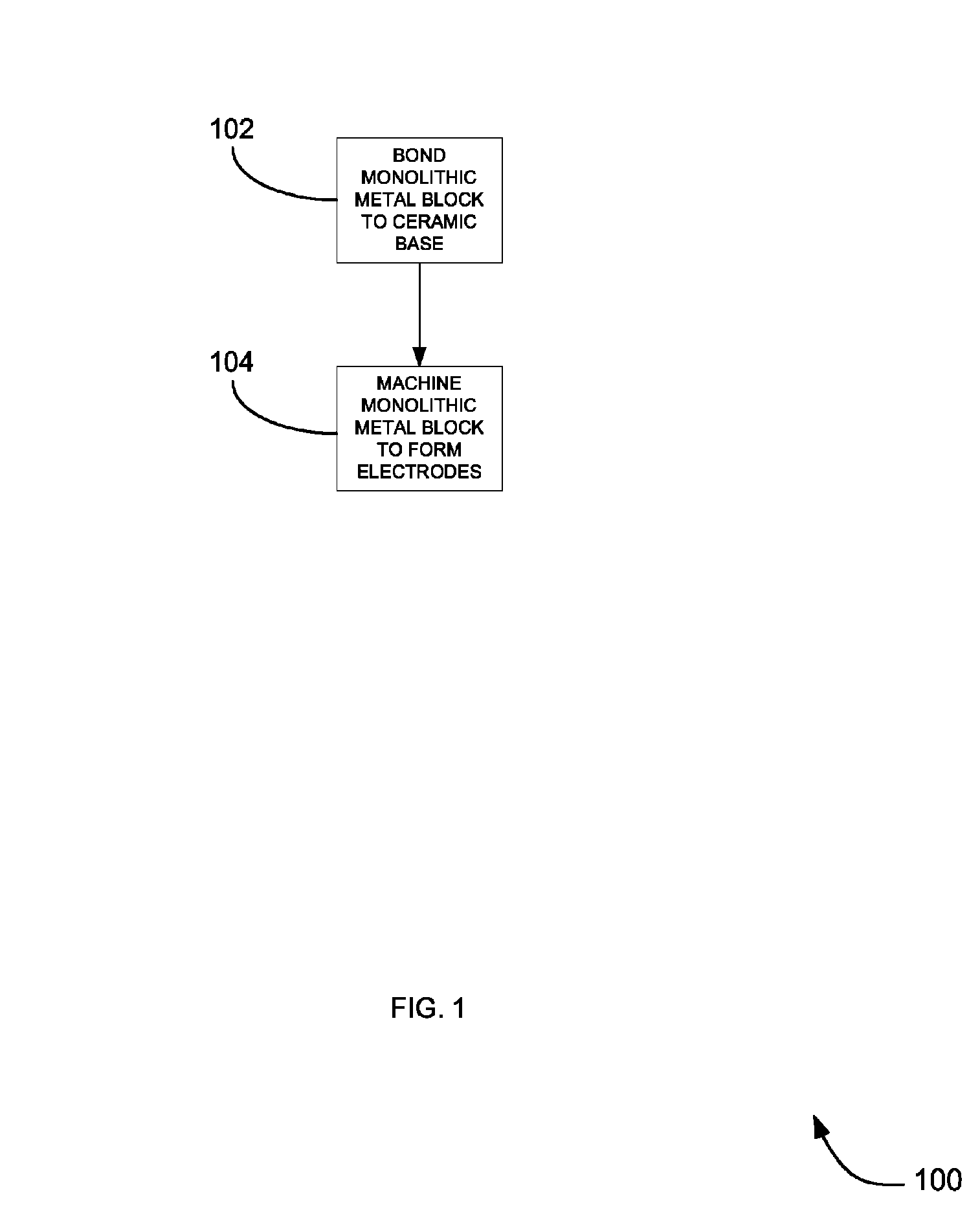
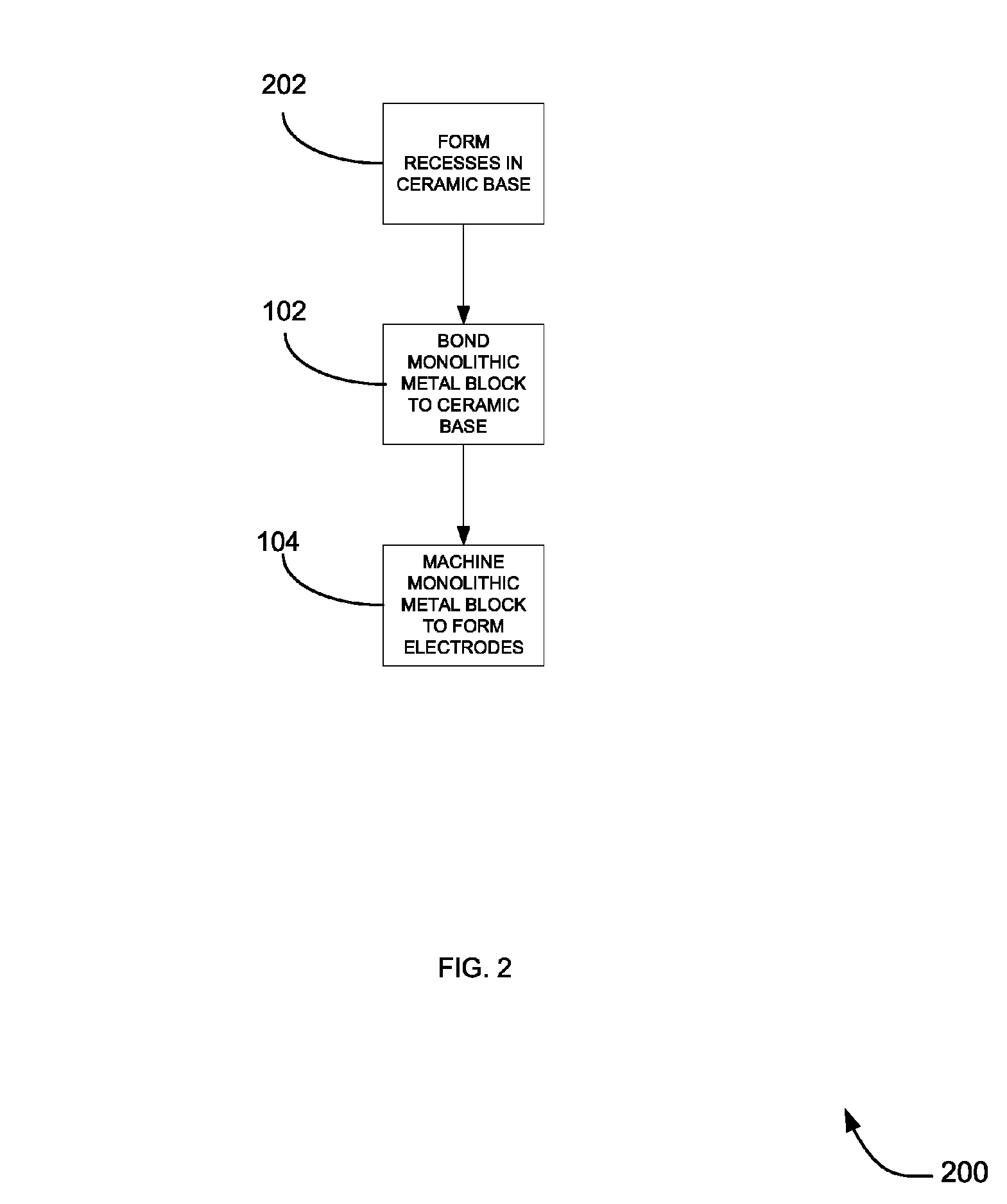
[0022]FIG. 1 is a flowchart of a method for producing a multi-electrode cathode for an X-ray tube according to an embodiment. System 100 includes the actions of bonding 102 a monolithic metal block 504 to a nonconductive base 402, and thereafter machining 104 the monolithic metal block...


PUM


Abstract

Apparatus and methods are provided through which a multi-electrode cathode assembly can be manufactured comprising bonding a monolithic metal block to the nonconductive base; and thereafter machining the block to form at least one electrode.

Description

FIELD OF THE INVENTION[0001]This invention relates generally to X-ray tubes, and more particularly to multi-electrode cathode X-ray tubes that allow for focal spot control and methods for manufacturing them.BACKGROUND OF THE INVENTION[0002]X-ray tubes typically consist of a cathode assembly opposing an anode assembly contained within a vacuum tube. The basic cathode assembly is a filament that is recessed in a cup-shaped structure. When energized by a filament power supply, the cathode's filament heats up to extremely high temperatures and electrons are boiled off. The anode, which is typically tungsten, is located at the opposite side of the X-ray tube and is oppositely charged from the cathode. The positively charged anode attracts the negatively charged electrons expelled from the cathode. The electrons are accelerated towards the anode at great speed and collide with the anode with great force. The interaction between the colliding electrons and the tungsten atoms in the anode c...

Claims


Application Information

Patent Timeline
Patent Type & Authority Patents(United States)
IPC IPC(8): H01J9/04
CPCH01J35/06H01J2235/068H01J35/064H01J35/066
Inventor LEMAITRE, SERGIO
Owner GENERAL ELECTRIC CO
Why Eureka
Try Eureka