
Methods of Manufacturing a Convertible Orthodontic Bracket by Machining

a technology of machining and convertible brackets, applied in the field of orthodontic brackets, can solve the problems of reducing strength, reducing overall treatment time, and limited strength of sintered bodies, and achieve the effects of reducing cross-sectional thickness, facilitating orderly, predictable, and easy removal of labial web covers

Inactive Publication Date: 2012-03-15
ULTRADENT PROD INC
View PDF5 Cites 2 Cited by
  • Summary
  • Abstract
  • Description
  • Claims
  • Application Information

AI Technical Summary

Benefits of technology

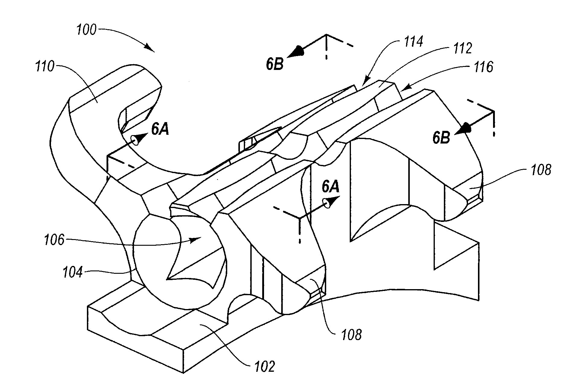
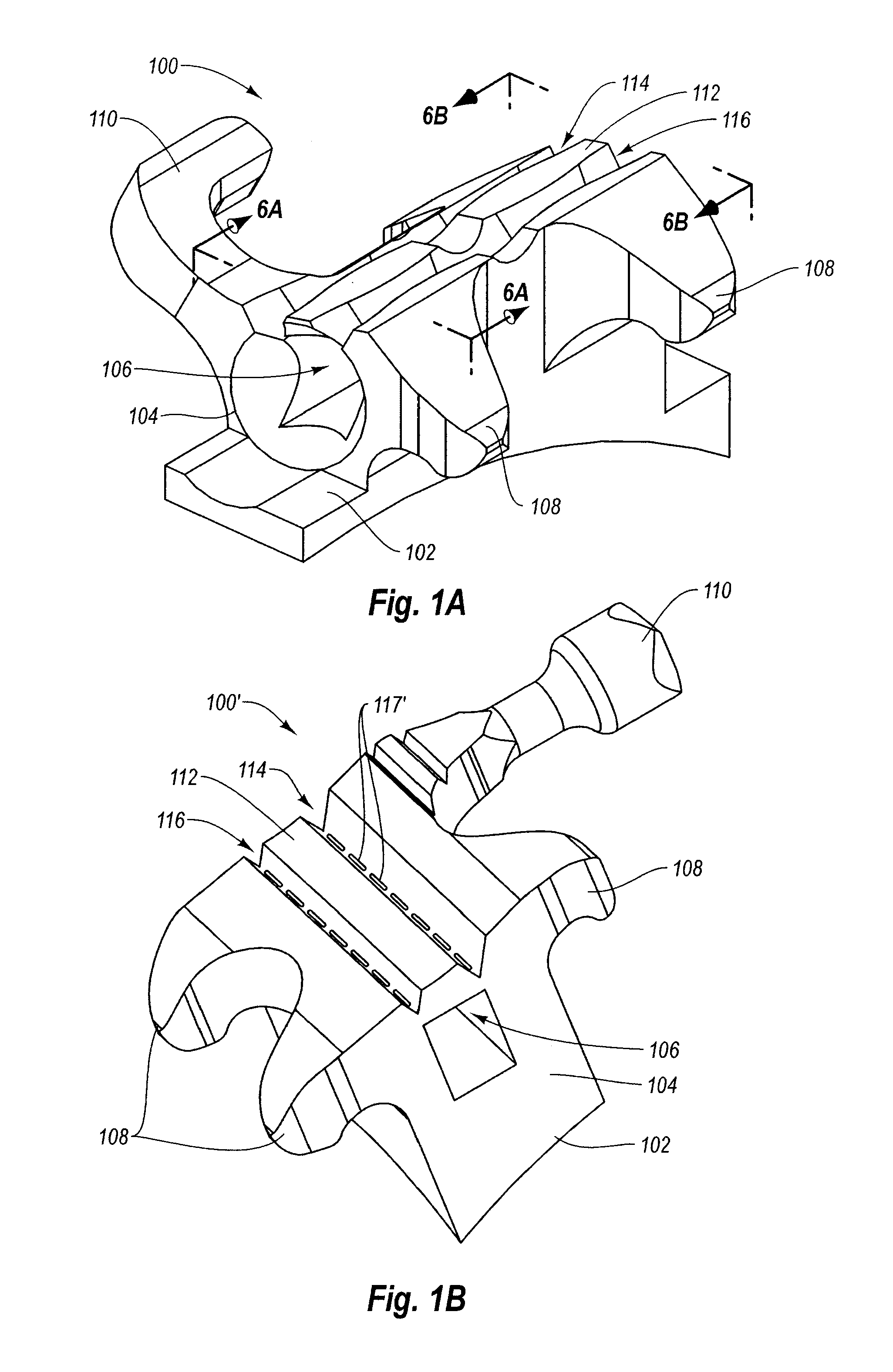
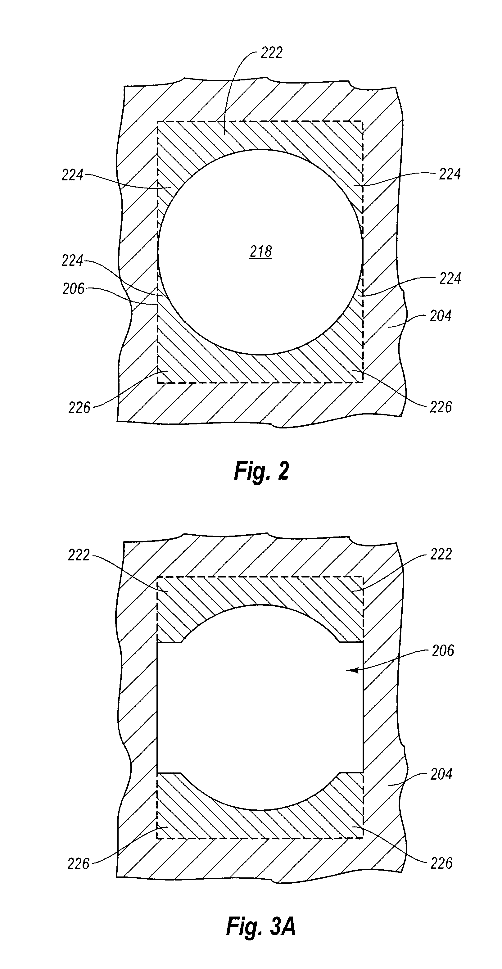
[0007]The present invention is directed to methods of manufacturing convertible orthodontic brackets that include a labial web cover which is selectively removable during orthodontic treatment. As such, the arch wire receptacle is a rectangular hole or tube closed on four sides rather than an open slot when the bracket is manufactured and during an early phase of treatment. According to the inventive manufacturing method, the arch wire hole is machined rather than formed by a metal injection molding and sintering process. At least one circular cross-sectioned pilot hole is formed so as to extend mesially-distally through the body of the orthodontic bracket. A shaping broach is then pushed or pulled through the pilot hole so as to form the desired rectangularly-shaped arch wire hole within the orthodontic bracket body. The area surrounding the labial web cover is also machined to form first and second connecting web regions of reduced cross-sectional thickness on either side of the labial web cover. These thinned connecting web regions facilitate orderly, predictable, and easy removal of the labial web cover when desired by the practitioner.
[0008]Such a machining method advantageously allows for the use of stronger, more dense metal materials (e.g., 17-4 and / or 17-7 class stainless steels). In addition, because the bulk metal material is not a sintered powder, the overall strength of the bracket manufactured according to the inventive method exhibits far greater strength and durability. For example, during a molding and sintering process, tiny voids can form within the body, thereby reducing strength. In addition, the strength of a sintered body is limited by the adhesion of the powder particles to one another after sintering. Finally, machining the brackets allows for tighter manufacturing tolerances, as molded and sintered brackets are known to shrink or otherwise deform an unpredictable amount during sintering. Narrower tolerances provide for better fit for the patient, which results in reduced overall treatment times.
[0010]In preferred embodiments, multiple pilot holes may be formed and / or multiple broaches employed. Such methods have advantageously been found to greatly reduce tool wear on the drill bits, end mills, and shaping broaches used to form the pilot holes and finish the rectangularly shaped hole. The reduction in tool wear is even greater than would be expected simply as a result of using multiple tools to perform a task.

Problems solved by technology

For example, during a molding and sintering process, tiny voids can form within the body, thereby reducing strength.
In addition, the strength of a sintered body is limited by the adhesion of the powder particles to one another after sintering.
Narrower tolerances provide for better fit for the patient, which results in reduced overall treatment times.
The ability to form such tiny holes is surprising, as those skilled in the art previously would have expected this manufacturing method to be unworkable as a result of severe tool wear and / or tool breakage.

Method used


Image

  • Methods of Manufacturing a Convertible Orthodontic Bracket by Machining
  • Methods of Manufacturing a Convertible Orthodontic Bracket by Machining
  • Methods of Manufacturing a Convertible Orthodontic Bracket by Machining

Examples


Embodiment Construction

I. Introduction

[0029]The present invention is directed to methods of manufacturing convertible orthodontic brackets, which include a selectively removable labial web cover that is removed (e.g., by peeling) intraorally by the practitioner part way through treatment. According to the inventive method of manufacture, a circular pilot hole may be formed so as to extend mesially-distally through the body of the orthodontic bracket. At least one shaping broach is then pushed or pulled through the pilot hole so as to form at least a portion of the desired rectangularly-shaped arch wire hole within the orthodontic bracket body. The area surrounding the labial web cover may also be machined to form first and second connecting web regions of reduced cross-sectional thickness on either side of the labial web cover. These thinned connecting web regions facilitate orderly, predictable, and easy peeling removal of the labial web cover when the practitioner desires.

II. Exemplary Convertible Ortho...


PUM

PropertyMeasurementUnit
Diameteraaaaaaaaaa
Diameteraaaaaaaaaa
Diameteraaaaaaaaaa

Abstract

Convertible orthodontic brackets (100) with a selectively removable labial web (112) are formed by machining. A circular pilot hole is formed so as to extend mesially-distally through the body of the orthodontic bracket (100). One or more shaping broaches are then pushed or pulled through the pilot hole so as to form a desired rectangularly-shaped arch wire hole (106) within the orthodontic bracket body (104). The area surrounding the labial web cover (112) is also machined to form first and second connecting web regions (114, 116) of reduced cross-sectional thickness on either side of the labial web cover (112). Manufacture by machining allows stronger more dense metals to be employed compared to manufacturing by metal injection molding.

Description

BACKGROUND OF THE INVENTION[0001]1. The Field of the Invention[0002]The present invention relates to orthodontic brackets and related methods of manufacture.[0003]2. The Relevant Technology[0004]Orthodontics is a specialized field of dentistry that involves the application of mechanical forces to urge poorly positioned or crooked teeth into correct alignment and orientation. Orthodontic procedures can be used for cosmetic enhancement of teeth, as well as medically necessary movement of teeth to correct underbites or overbites. For example, orthodontic treatment can improve the patient's occlusion and / or enhanced spatial matching of corresponding teeth.[0005]The most common form of orthodontic treatment involves the use of orthodontic brackets and wires, which together are commonly referred to as “braces.” Orthodontic brackets are small slotted bodies configured for direct attachment to the patient's teeth or, alternatively, for attachment to bands which are, in turn, cemented or oth...

Claims


Application Information

Patent Timeline
IPC IPC(8): A61C7/14B21F43/00
CPCY10T29/49568A61C7/14
Inventor LEWIS, PAUL E.WOOD, TIMOTHY V.KRUMPELMANN, MICHAEL J.
Owner ULTRADENT PROD INC
Learn More