Gearbox for a wind turbine

a wind turbine and gearbox technology, applied in the direction of toothed gearings, motors, engine fuctions, etc., can solve the problems of reducing the working efficiency of the ring wheel unit, restricting the play between the flanks of the teeth of the gear wheel, and overloaded gear wheels and the bearings of the planet wheels. the effect of alignment error

Inactive Publication Date: 2010-11-09
HANSEN TRANSMISSIONS INT NV
View PDF11 Cites 164 Cited by
  • Summary
  • Abstract
  • Description
  • Claims
  • Application Information

AI Technical Summary

Benefits of technology

[0016]An advantage of such a gearbox for a wind turbine according to the invention is that the above-mentioned alignment error that occurs as a result of deformations of the main bearings, the planet carrier, the driving shaft and / or the housing or as a result of plays can be absorbed or compensated for, as the elastic part of the housing makes it possible for the part of the housing in which the ring wheel and the additional bearing have been provided can move in an axial or radial direction in relation to the part of the housing in which the main bearings are embedded.
[0026]For, the larger the stiffness of the main bearings, the smaller the alignment error will be at the additional bearing, the less the elastic part must be deformed so as to compensate the alignment error, the less load the additional bearing will thus be subjected to.

Problems solved by technology

A disadvantage of the known embodiments is that, while the wind turbine is operational, the main bearings are subject to a certain elastic deformation under the influence of the rotor loads, which inevitably results in a certain play in the main bearings, which will cause an alignment error at the ring wheel unit which hinders the good working of the ring wheel unit.
For, a result of the above-mentioned alignment error is that the plays between the flanks of the teeth of the gear wheels can be restricted in some cases or can be entirely absent or, the other way round, may increase.
A disadvantage of all this is that an uneven load of the gear wheels is obtained and that the normal interplay of forces between the gear wheels is disturbed, which will result in the gear wheels and the bearings of the planet wheels being overloaded.

Method used


Image

  • Gearbox for a wind turbine
  • Gearbox for a wind turbine
  • Gearbox for a wind turbine

Examples


Embodiment Construction

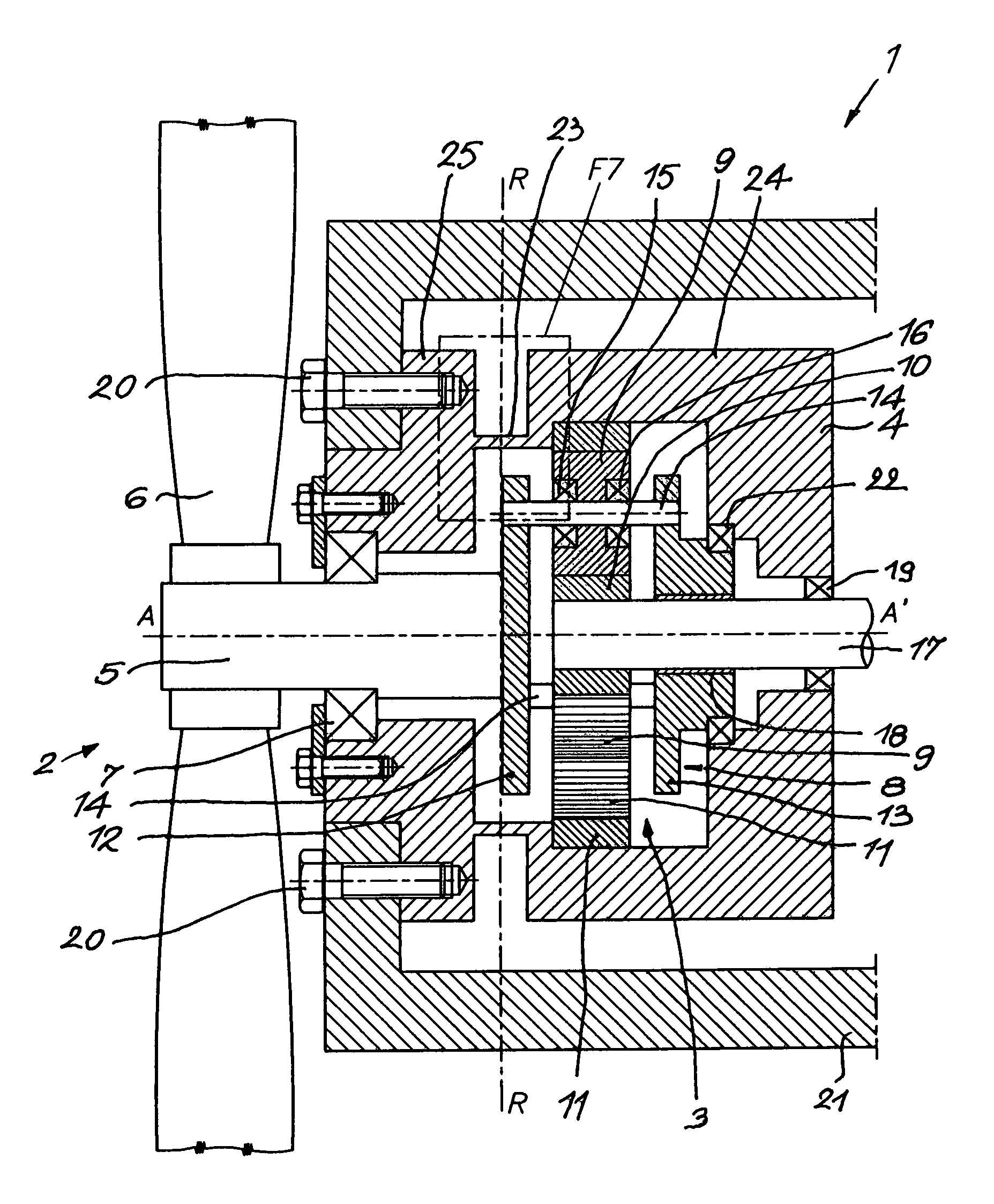
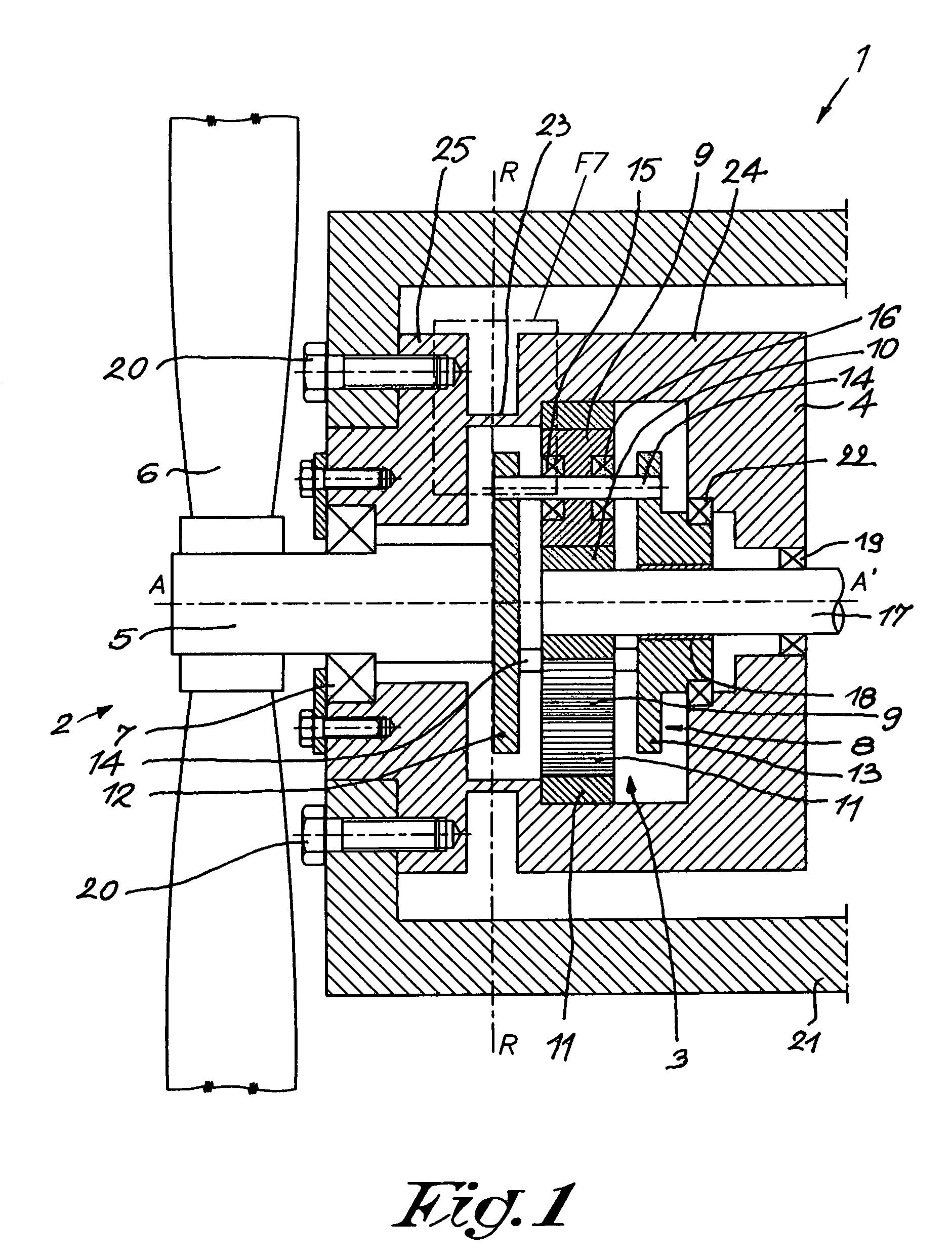
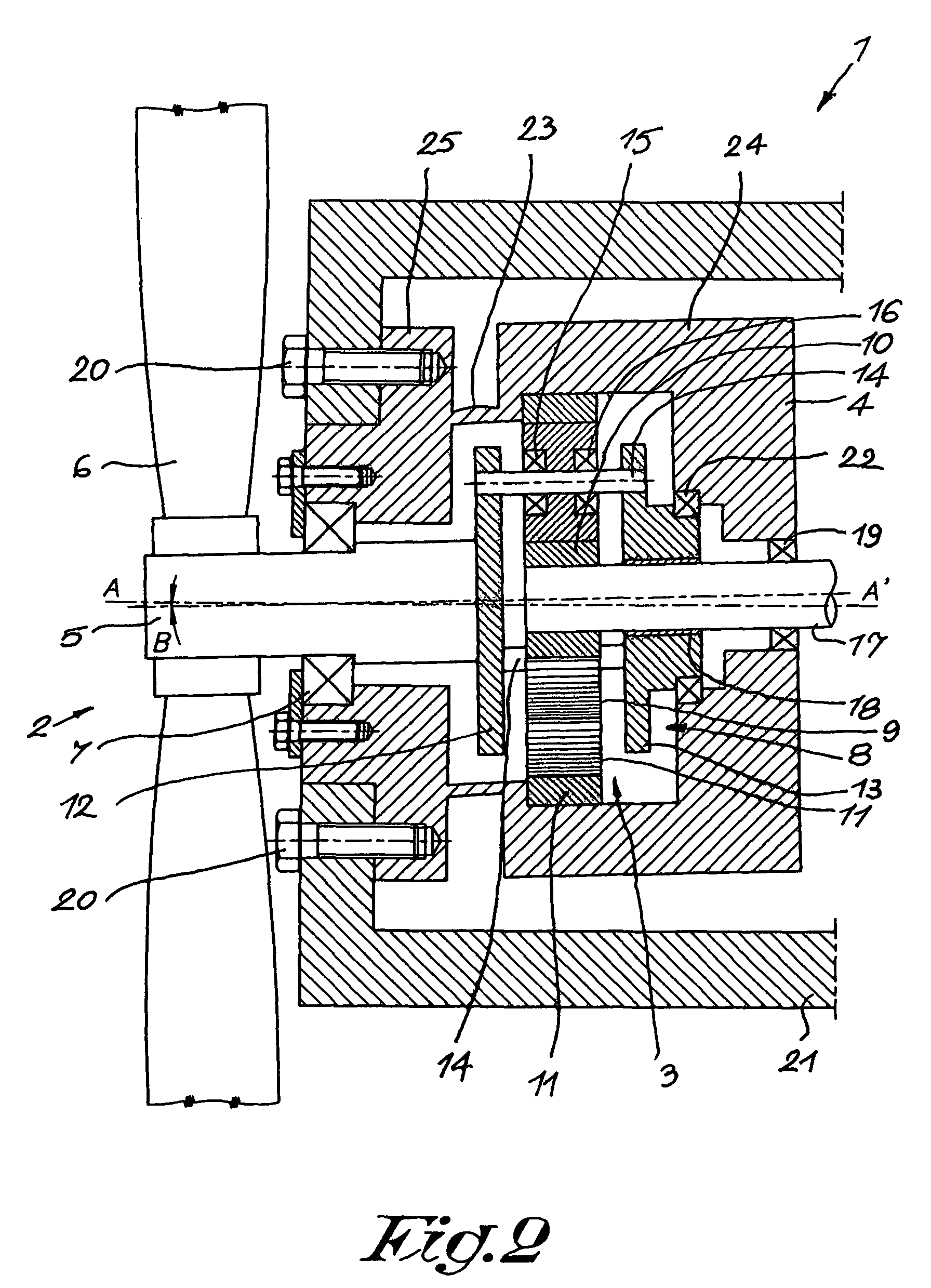
[0039]The gearbox 1 for a wind turbine 2 according to the invention represented in FIG. 1 consists of ring wheel unit 3 provided in a housing 4; a driving shaft 5 which is coupled to the rotor 6 of the wind turbine 2 and a main bearing 7 which supports the driving shaft or rotor shaft 5 in a rotating manner in the housing 4.

[0040]The ring wheel unit 3 consists of a planet carrier 8 on which have been provided planet wheels 9, in this case three planet wheels 9 in total, whereby these planet wheels 9 work in conjunction with a sun wheel 10 and ring wheel 11 which is fixed to the housing 4 of the gearbox 1 in a non-rotating manner.

[0041]The planet wheels 9 can rotate in relation to the planet carrier 8

[0042]To this end, the planet carrier 8 in the given example consists of a first part 12 and a second part 13, which parts are connected to each other by means of shafts 14.

[0043]As an alternative, such a planet carrier 8 of what is called the “cage” type can also be made of a single pie...


PUM


Abstract

A gearbox for a wind turbine includes a ring wheel unit provided in a housing; a driving shaft designed to be coupled to the rotor of the wind turbine and a single main bearing or a pair of main bearings which rotatably support the driving shaft in the housing. The ring wheel unit is formed of a sun wheel, a planet wheel, ring wheel which is fixed to the housing in a non-rotating manner and a planet carrier which is rigidly connected to the driving shaft. An additional bearing rotatably supports the planet carrier or the driving shaft relative to the housing. Between the part of the housing having the main bearing or the main bearings and the part of the housing with the additional bearing and the ring wheel, an elastic part is provided with relative torsional stiffness, yet relatively flexible to loads in the axial and / or radial direction.

Description

BACKGROUND OF THE INVENTION[0001]1. Field of the Invention[0002]The present invention concerns a gearbox for a wind turbine.[0003]In particular, the present invention concerns a gearbox for a wind turbine which consists of ring wheel unit provided in a housing; a driving shaft designed to be coupled to the rotor of the wind turbine and a single main bearing or a pair of main bearings which support the driving shaft such that it can be rotated in the housing, whereby the ring wheel unit is formed of a sun wheel, a planet wheel, ring wheel which is fixed to the housing in a non-rotating manner and a planet carrier which is rigidly fixed to the driving shaft.[0004]2. Discussion of the Related Art[0005]Such gearboxes for wind turbines are already known, whereby the driving shaft is coupled to the rotor of a wind turbine and whereby the sun wheel of the gear unit drives for example a generator.[0006]In the conventional embodiments, the housing of the gearbox is made of several pieces, wh...

Claims


Application Information

Patent Timeline
Patent Type & Authority Patents(United States)
IPC IPC(8): F16H3/72F16H57/08
CPCF03D11/02F16H1/48F05B2260/40311F16H1/2818Y02E10/722F03D15/00F03D15/10F03D80/70Y02E10/72
Inventor SMOOK, WARREN GREGORY
Owner HANSEN TRANSMISSIONS INT NV
Why Eureka
Try Eureka