Kung fu training device

a training device and kung fu technology, applied in the field of kung fu training devices, can solve the problems of loss of positioning function, easy disengagement of annularly-disposed teeth from each other, and loss of positioning function

Inactive Publication Date: 2010-11-09
CHEN YI LIN
View PDF3 Cites 34 Cited by
  • Summary
  • Abstract
  • Description
  • Claims
  • Application Information

AI Technical Summary

Benefits of technology

[0009]To achieve the above object, a kung fu training device of the present invention includes a positioning portion, a body pole, a shoulder portion, two joint portions, two arm portions and several pins. Polygonal holes and corresponding polygonal poles are disposed on pivoting ends of the shoulder, the first and second joints of the joint portions, and the arm connectors of the arm portions respectively. Thereby...

Problems solved by technology

However, not every trainee has the same height and body size, nor do all the simulating enemies have the same height, body size, attack and defense tricks.
However, such annularly-disposed teeth are easily disengaged from each other due to the overloaded instantaneous force output by ...

Method used


Image

  • Kung fu training device
  • Kung fu training device
  • Kung fu training device

Examples


first embodiment

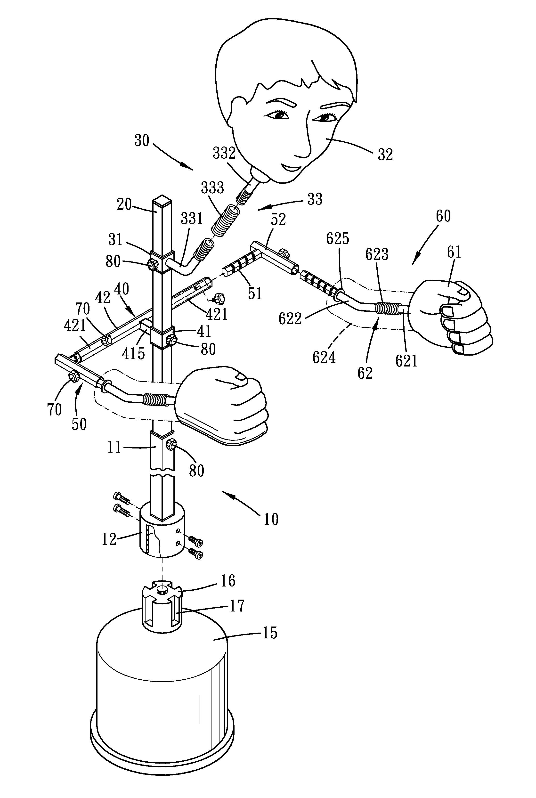
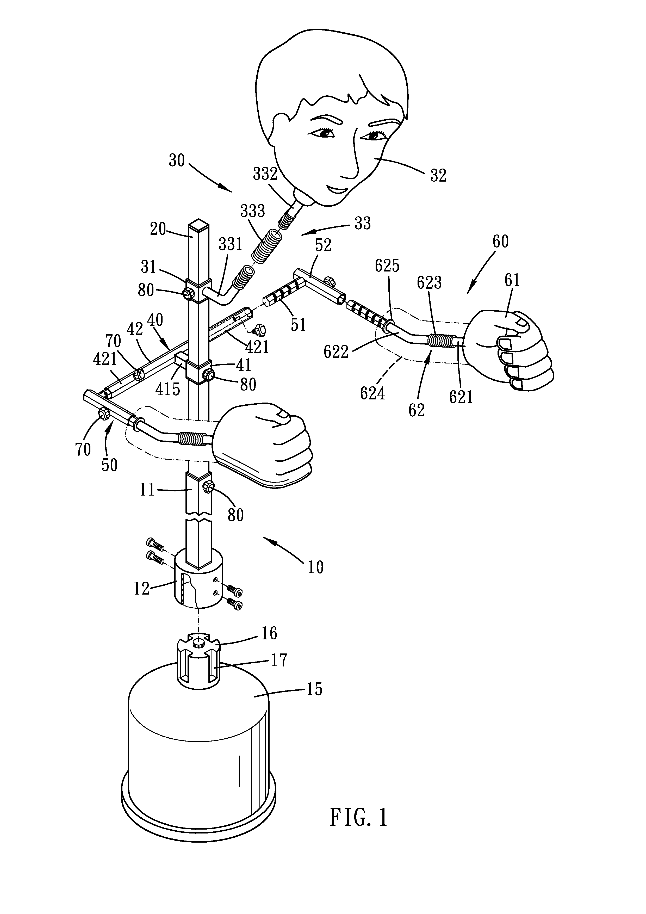
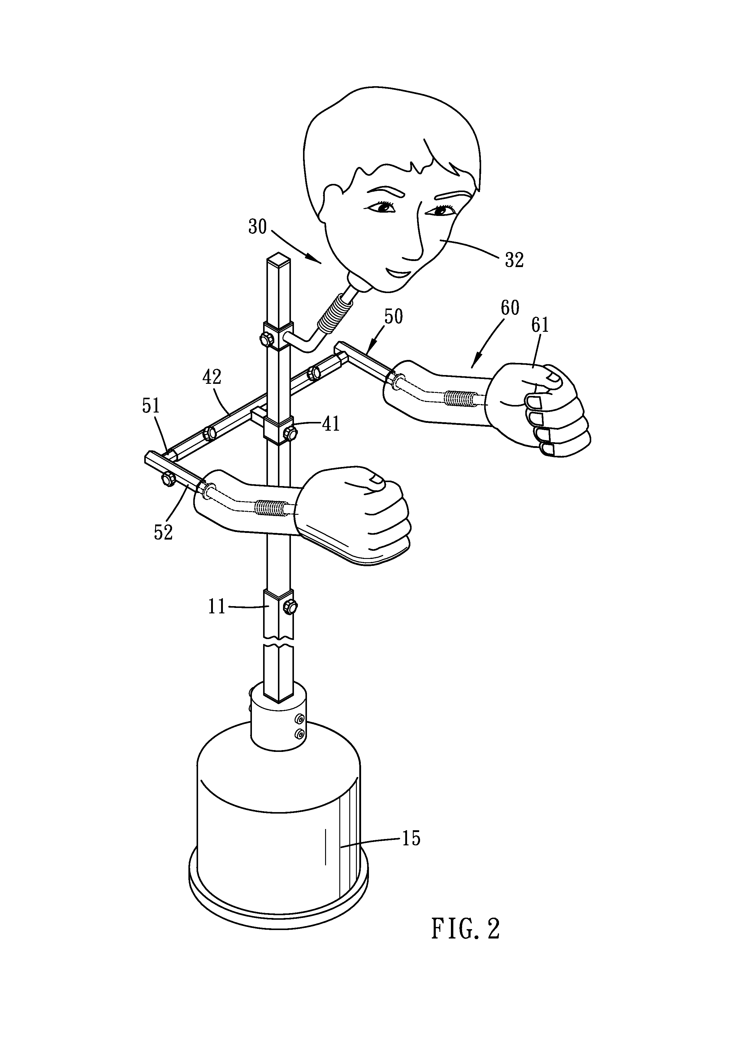
[0021]Please refer to FIG. 1 to FIG. 3 for the present invention. A kung fu training device includes a positioning portion 10, a base 15, a body pole 20, a head portion 30, a shoulder portion 40, two joint portions 50, two arm portions 60 and several pins 70.

[0022]The positioning portion 10 is a tube with a rectangular, any polygonal or other geometric profile. The positioning portion 10 has a socket 11 with an opening facing upward. A bottom end of the positioning portion has an enlarged sleeve 12, which has a larger diameter than that of a circumcircle of the socket's 11 profile. The sleeve 12 mates with a protrusion 16 disposed on the base 15. Several screws are used to further fix the sleeve 12 to the protrusion 16. In addition, at least one groove 17 may be axially formed on the protrusion, and at least one rib (not shown) may be formed on the inner walls of the sleeve 12 to engage with the groove 17 in an unrotatable manner. The base 15 is heavy weighted so that the center of ...

second embodiment

[0029]Refer to FIG. 5 and FIG. 6 for the present invention. Both the forearm 621 and the upperarm 622 have an arm coil spring 623 and two sub-sections respectively. Therefore, the arm connector 62 may slightly deform as the fist pad 61 being punched. For training safety and aesthetic purpose, two foam sleeves 624 are used to enclose the arm connectors 62 respectively. Furthermore, each arm connector 62 has a flange 625 disposed close to its corresponding polygonal hole, and the foam sleeve 624 is disposed between the flange 625 and the fist pad 61 so that it is free from being inadvertently stocked in the polygonal hole. The fist pad 61, just like the head pad 32, may be an air bag, a foaming object or the same to provide suitable feedback.

[0030]As shown in FIG. 7, the positioning portion 10 may be bent to have an angle of 90 degrees, and its distal end is therefore suitable to fix on a wall.

[0031]As shown in FIG. 8, a cushion pad 111 may be provided to surround the socket 11 for tr...


PUM


Abstract

A kung fu training device of the present invention includes a positioning portion, a body pole, a shoulder portion, two joint portions, two arm portions and several pins. Polygonal holes and corresponding polygonal poles are disposed on pivoting ends of the shoulder, the first and second joints of the joint portions, and the arm connectors of the arm portions respectively. Thereby, the fist pads disposed on the distal ends of the arm portions are height-adjustable and angle-adjustable about the body pole, and the heights of the shoulder portion and the head portion are also adjustable. As a result, the training device of the present invention is suitable for the trainees with different body sizes to simulate fighting with simulating enemies with different body sizes, so as meet the trainees' need.

Description

BACKGROUND OF THE INVENTION[0001]1. Field of the Invention[0002]The present invention relates to a kung fu training device, more particularly to a training device that can adjust the heights of and the relative distances between three hitting pads.[0003]2. Description of the Prior Art[0004]One of the most typical kung fu training device having three hitting portion is called wooden dummy. A wooden dummy has three hitting pole with fixed angle and relative position for the trainee to practice attack and defense tricks, and eventually it becomes a popular kung fu training device.[0005]For realistic training or other purposes, the wooden dummy is constantly promoted, such as disclosed in U.S. Pat. No. 3,250,533, U.S. Pat. No. 4,387,892, U.S. Pat. No. 4,593,900, U.S. Pat. No. 4,765,609, U.S. Pat. No. 4,770,412, U.S. Pat. No. 5,256,069, U.S. Pat. No. 5,700,230, U.S. Pat. No. 5,899,835, U.S. Pat. No. 6,152,863 and U.S. Pat. No. 6,808,477.[0006]However, not every trainee has the same heigh...

Claims


Application Information

Patent Timeline
IPC IPC(8): A63B21/00
CPCA63B69/004A63B69/34A63B2225/093A63B2244/10A63B69/215A63B69/22
Inventor CHEN, YI-LIN
Owner CHEN YI LIN
Why Eureka
Try Eureka