Vehicle charging, monitoring and control systems for electric and hybrid electric vehicles

a technology of monitoring control system and electric motor vehicle, which is applied in the direction of hybrid vehicles, battery/fuel cell control arrangement, electric devices, etc., can solve the problems of premature battery failure and uncharged batteries, and achieve the effect of maximizing the acceleration availabl

Active Publication Date: 2010-11-09
POWER TECH HLDG LLC
View PDF75 Cites 79 Cited by
  • Summary
  • Abstract
  • Description
  • Claims
  • Application Information

AI Technical Summary

Benefits of technology

[0008]It is yet another object of the present invention to provide a distributed battery charging system and to prevent uneven battery charging and premature battery failure in electric and hybrid electric vehicles.
[0024]An SES preferably includes the batteries (which can be of any chemistry or type), battery enclosure / tray, thermal management system, battery charger and microprocessor-based Battery Management System (BMS). The BMS monitors the batteries, controls the charger and thermal management system and communicates via CAN with the MEC. The BMS reports critical information to the MEC on overall battery pack and individual battery modules. The BMS also performs its own “internal” operations such as battery monitoring, equalization and charging. The BMS provides the MEC with battery state of charge information, so that the MEC can provide the operator with a “miles to empty” indication and with any critical errors which may exist within the its SES. Multiple SES units of different voltages and current capacities can be used on a vehicle, either connected in series, parallel or stand-alone.Traction Drive System (TDS)
[0025]The Traction Drive System (TDS) preferably includes the traction motor, motor controller with Inverter and a Driver Interface Node (DIN). The TDS is the part of the system, which creates the path between the driver and the wheels, specifically processing accelerator and brake pedal feedback, in order to move and stop the vehicle. The TDS receives critical information from the Master Events Controller (MEC), (as provided by the Stored Energy System (SES) units and other vehicle sub-systems connected to the VMCS), in order to maximize available acceleration and allowable regenerative braking, based on the condition of the SES units.Auxiliary Power Unit (APU)
[0026]The Auxiliary Power Unit (APU) preferably includes a heat engine, alternator, fuel storage and power conversion electronics. The APU system can be configured to operate on a variety of fuels and generates electricity to charge the battery packs within the SES units. Alternatively, a fuel cell can be used. The MEC sends commands to the APU through the APU Control Node in order to establish the correct time and power level for APU operation. The APU provides the MEC with critical information such as current engine operating statistics along with fuel level so the MEC can provide the driver with a “miles to empty” indication and with any errors which may exist within the APU.

Problems solved by technology

Recharging batteries configured in the stated, segmented configuration with a bulk-charging device is not optimal, resulting in uneven battery charging and premature battery failure.

Method used


Image

  • Vehicle charging, monitoring and control systems for electric and hybrid electric vehicles
  • Vehicle charging, monitoring and control systems for electric and hybrid electric vehicles
  • Vehicle charging, monitoring and control systems for electric and hybrid electric vehicles

Examples


Embodiment Construction

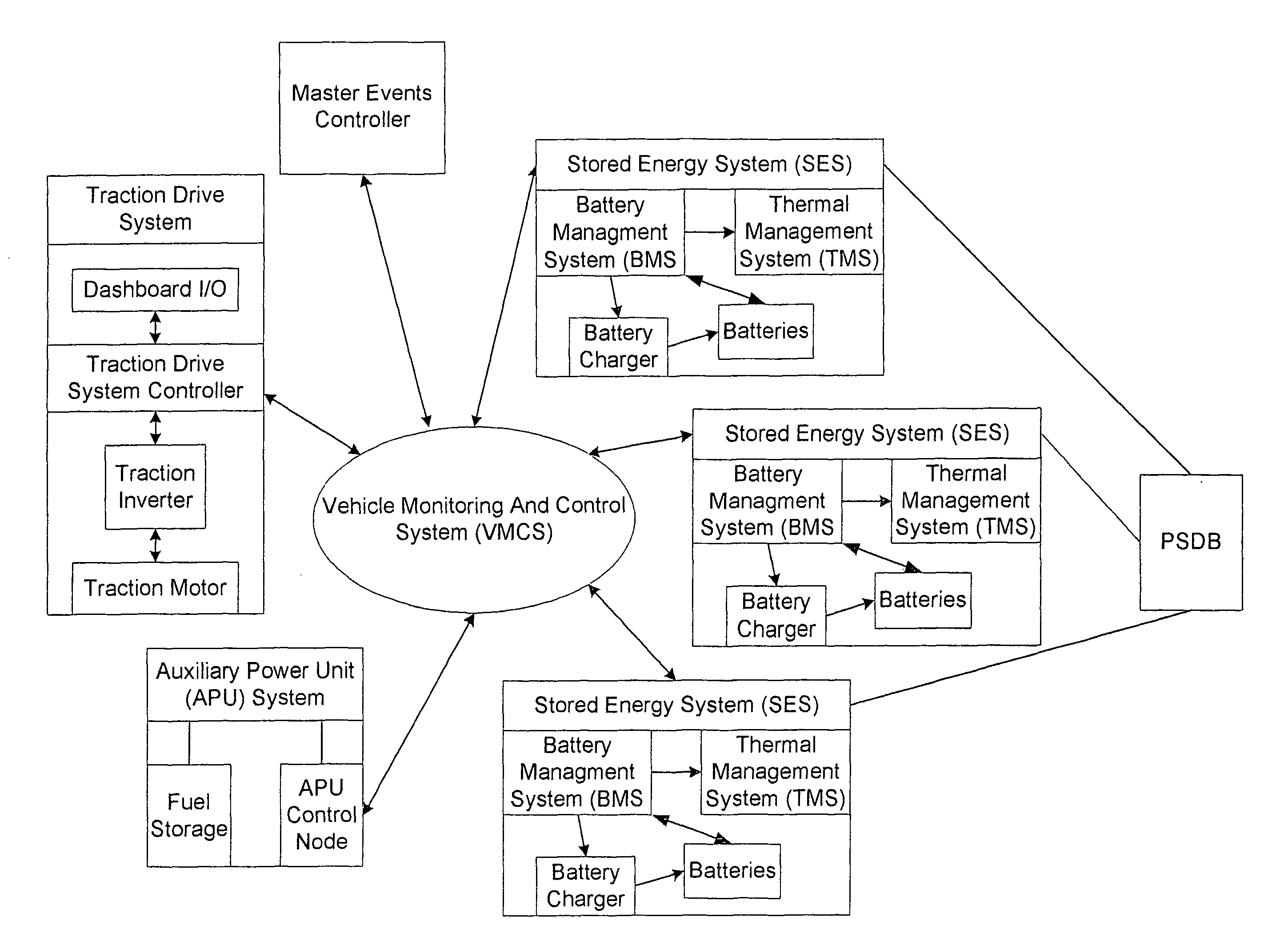
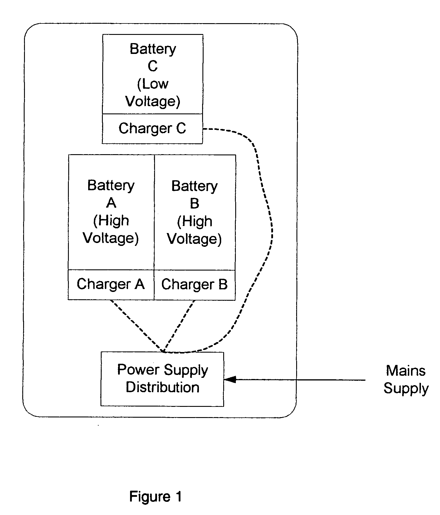
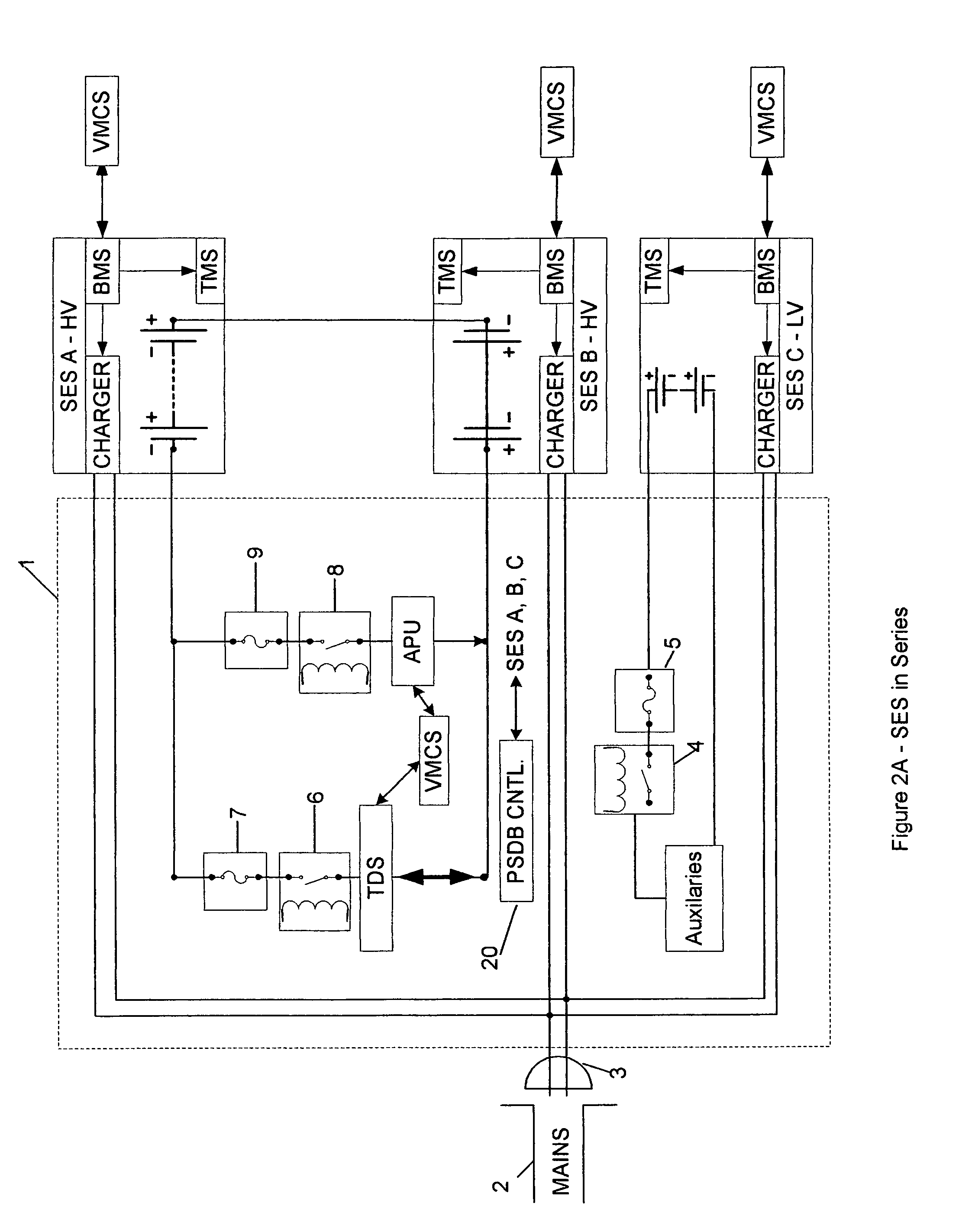
[0031]FIG. 1 is an illustration showing an example of the distributed charging system of this invention. The illustration of FIG. 1 shows three battery packs A, B and C having different nominal voltages. Battery compartment A and battery compartment B are normally connected in series during vehicle operation in order to achieve a voltage double the rated voltage of each individual battery compartment. Battery compartment C is a low voltage battery pack, which is used to supply power to the vehicle auxiliaries.

[0032]Each battery compartment in FIG. 1 is a complete Stored Energy System (SES), complete with Battery Management System (BMS) and other control, measurement and communication blocks, such as a Thermal Management System (TMS) and battery charger. During the period when the vehicle is charged, each Stored Energy System (SES) charges its own batteries by using its own charger, which is controlled by its own BMS. Battery charger A, charges batteries in Stored Energy System (SES)...


PUM


Abstract

A distributed charging system for electric and hybrid electric vehicles includes multiple battery packs of different voltages including high voltage battery packs and one or more low voltage battery packs, each having separate and independent charging systems and multiple sources of electric power. Electric power is distributed from the sources of electric power separately to each of the independent charging systems. A drive system for the electric or hybrid electric vehicle includes a stored energy system made up of these multiple battery packs and a master events controller controlling at least one of a) a traction drive system including a motor and controller for receiving driving electric energy from a stored energy system for propulsion of the vehicle, b), an auxiliary power system for recharging the battery packs and c) a vehicle monitoring and control network for controlling the operation of, and monitoring all bus systems in the vehicle.

Description

CROSS REFERENCE TO RELATED APPLICATIONS[0001]This application claims the benefit, under 35 U.S.C. 119(e) of U.S. Provisional Application No. 60 / 642,501, filed Jan. 10, 2005 and U.S. Provisional Application No. 60 / 642,499, filed Jan. 10, 2005, which are hereby incorporated by reference.FIELD OF THE INVENTION[0002]The present invention relates to energy distribution, monitoring and control systems for hybrid electric and electric motor vehicles. More particularly, the present invention is directed to electric and hybrid electric off-road and on-road vehicles, which use solely a battery pack or a battery and electric generator combination to supply energy for propulsion.BACKGROUND OF THE INVENTION[0003]Electric and hybrid electric vehicles sometimes require the use of a plurality of battery compartments in order to meet the total voltage and / or capacity requirements or to supply auxiliary systems requiring a separate battery compartment. For example, two battery strings or battery pack...

Claims


Application Information

Patent Timeline
Patent Type & Authority Patents(United States)
IPC IPC(8): H02J7/00
CPCB60L3/0046B60L11/126B60L11/1816B60L11/1853B60L11/1861B60L11/1866B60L11/1868B60W10/26H02J7/0019B60L3/12Y02T10/7061B60L2240/545B60W20/00Y02T10/6217Y02T10/7005Y02T10/7044Y02T10/7055Y02T10/7066Y02T10/7077Y02T90/14Y02T10/7072B60L53/14B60L50/62B60L58/18B60L58/12B60L58/22B60L58/20B60L58/24Y02T10/62Y02T10/70H02J7/00B60W2710/242B60W20/10B60W10/24
Inventor AMBROSIO, JOSEPH MARIOSFAKIANOS, KONSTANTINOS
Owner POWER TECH HLDG LLC
Why Eureka
Try Eureka