Dual mode vehicle blind spot system

a blind spot and dual-mode technology, applied in the field of sensor systems, can solve problems such as blind spots

Active Publication Date: 2010-11-09
FCA US
View PDF21 Cites 28 Cited by
  • Summary
  • Abstract
  • Description
  • Claims
  • Application Information

AI Technical Summary

Problems solved by technology

Although the use of side mirrors can assist, there may be blind spots.

Method used


Image

  • Dual mode vehicle blind spot system
  • Dual mode vehicle blind spot system
  • Dual mode vehicle blind spot system

Examples


Embodiment Construction

[0015]The following description is merely exemplary in nature and is in no way intended to limit the disclosure, its application, or uses. For purposes of clarity, the same reference numbers will be used in the drawings to identify similar elements. As used herein, the term module refers to an Application Specific Integrated Circuit (ASIC), an electronic circuit, a processor (shared, dedicated, or group) and memory that execute one or more software or firmware programs, a combinational logic circuit, and / or other suitable components that provide the described functionality. As used herein, the phrase at least one of A, B, and C should be construed to mean a logical (A or B or C), using a non-exclusive logical or. It should be understood that steps within a method may be executed in different order without altering the principles of the present disclosure.

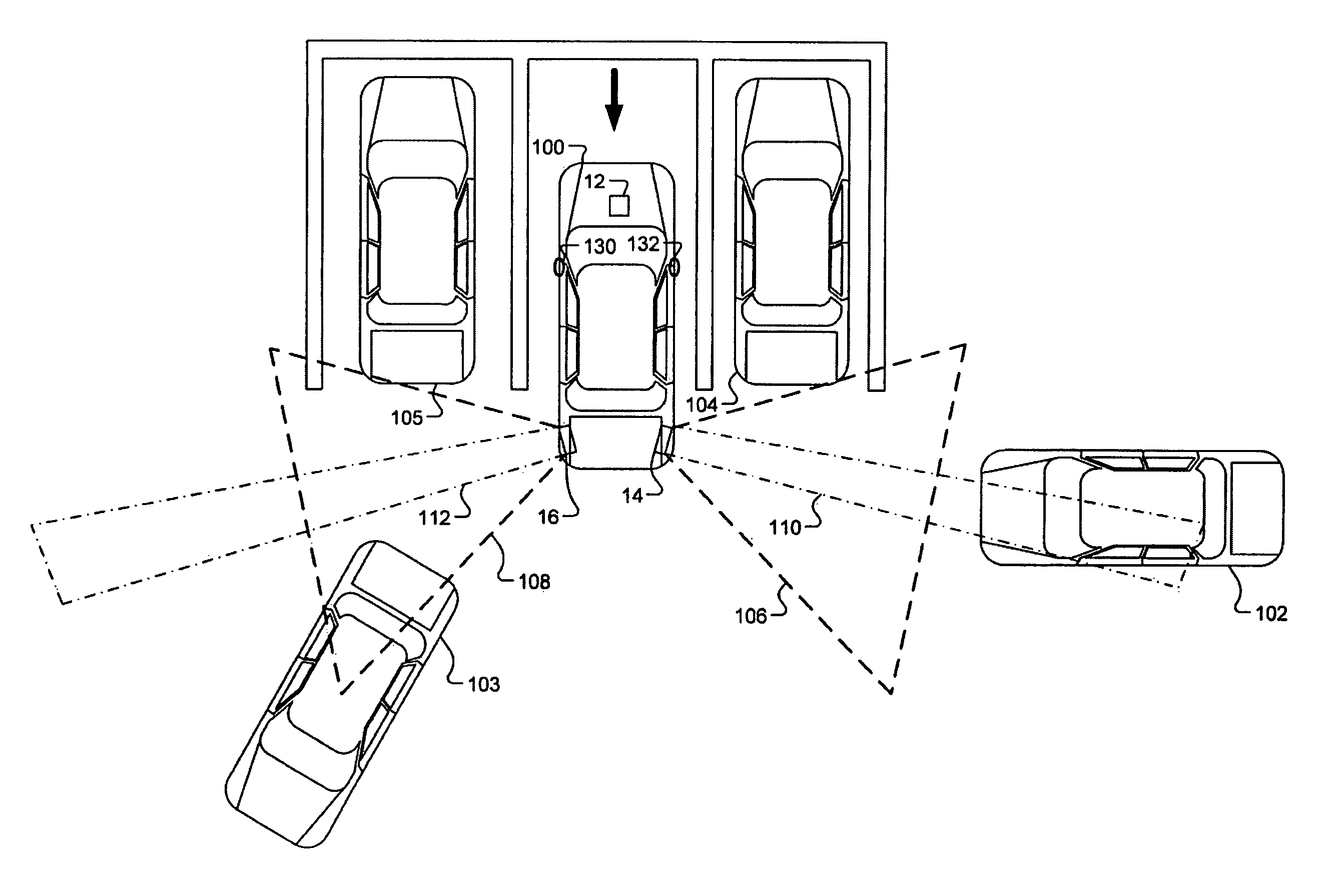
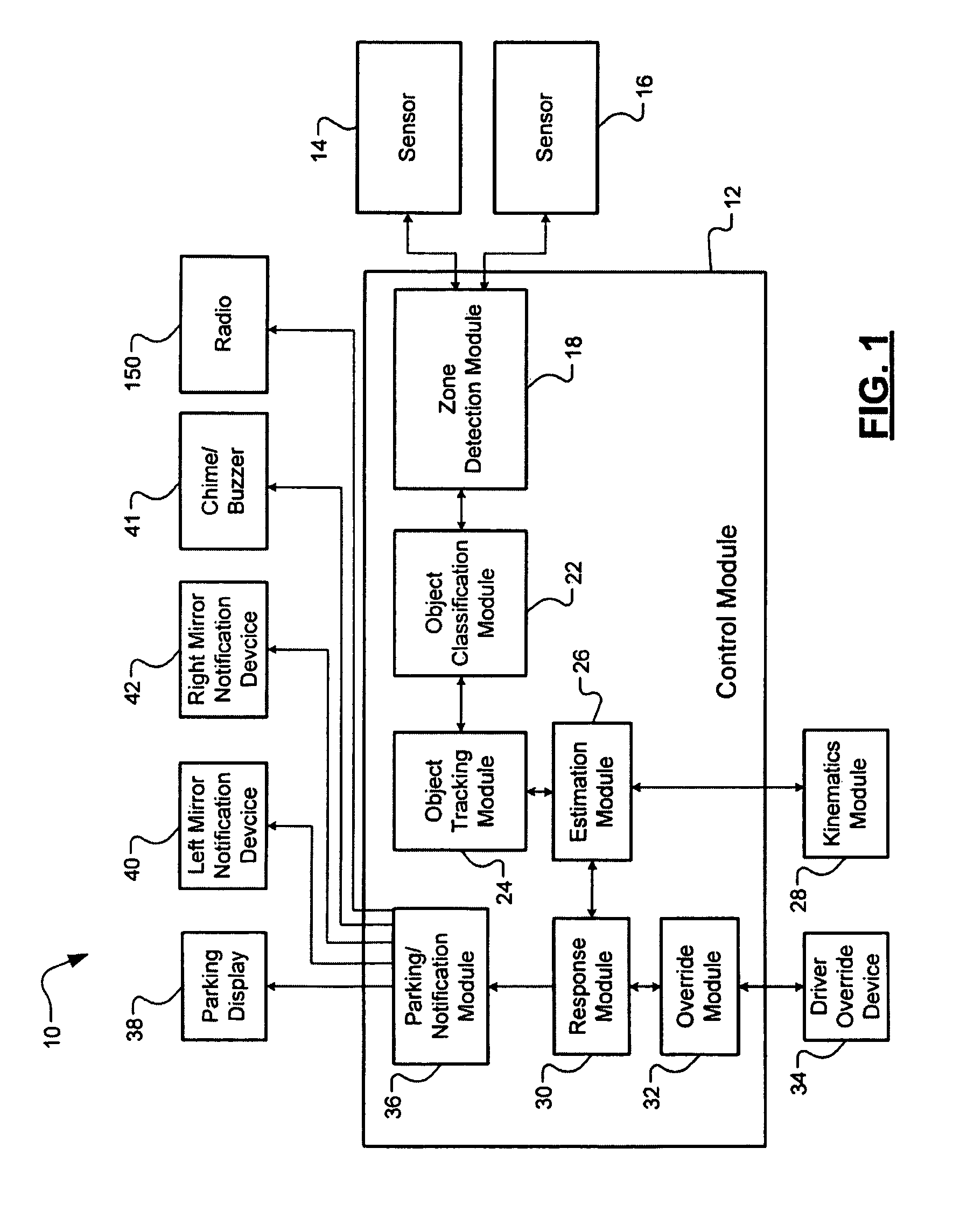
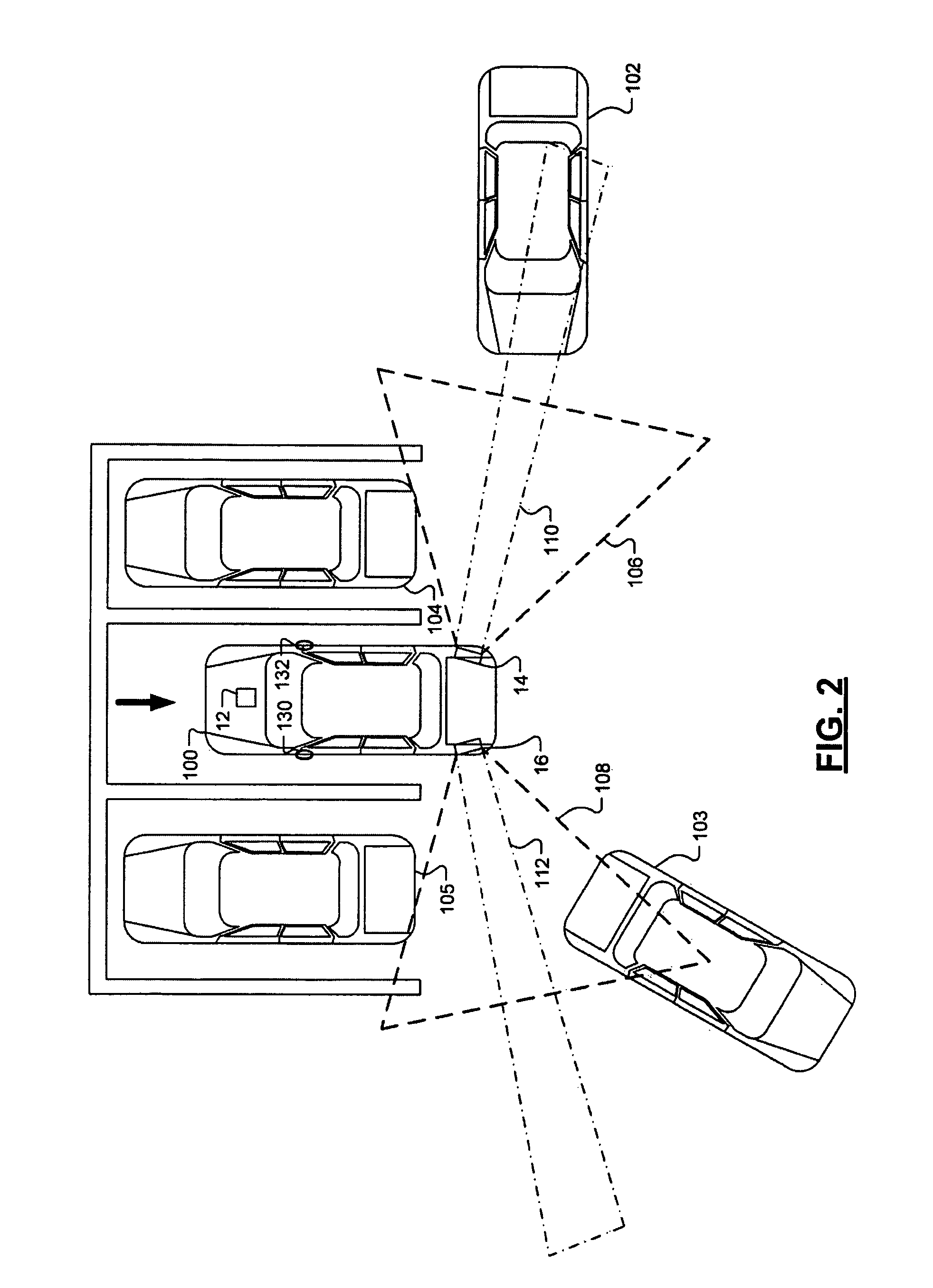
[0016]The present disclosure includes a vehicle proximity system that controls remote sensors in near and far modes.

[0017]Referrin...


PUM


Abstract

A proximity sensor system for a vehicle in reverse includes a zone detection module. The zone detection module switches a first remote sensor from a first mode corresponding to a near zone rearward of the vehicle to a second mode corresponding to a far zone rearward of the vehicle. The near zone includes an area of coverage wider and shorter in range than an area of coverage of the far zone. A response module responds to first objects in the near zone and selectively responds to second objects in the far zone when the second objects are in motion.

Description

CROSS REFERENCE TO RELATED APPLICATION[0001]This application claims the benefit of U.S. Provisional Patent Application Ser. No. 60 / 887,870, filed on Feb. 2, 2007.FIELD OF THE DISCLOSURE[0002]The present disclosure relates to sensor systems and more particularly to remote sensing systems for vehicles.BACKGROUND OF THE DISCLOSURE[0003]The background description provided herein is for the purpose of generally presenting the context of the disclosure. Work of the presently named inventors, to the extent it is described in this background section, as well as aspects of the description that may not otherwise qualify as prior art at the time of filing, are neither expressly nor impliedly admitted as prior art against the present disclosure.[0004]Drivers are often required to exercise judgment in the maneuvering of vehicles with respect to other objects that may be stationary or in motion. Such objects may be street signs, pedestrians, or other vehicles. This is particularly apparent when a...

Claims


Application Information

Patent Timeline
Patent Type & Authority Patents(United States)
IPC IPC(8): B60Q1/00
CPCB62D15/027G08G1/16G08G1/168G08G1/165G08G1/166
Inventor BUCKLEY, STEPHEN J.BASSIER, MICHAELZORATTI, PAUL
Owner FCA US
Why Eureka
Try Eureka