Microphone positioning structure

a positioning structure and microphone technology, applied in the direction of piezoelectric/electrostrictive transducers, earpiece/earphone manufacture/assembly, transducer types, etc., can solve the problems of insufficient vacuum generation technology, inability to achieve the desired effect, and inability to dissipate sound

Active Publication Date: 2010-11-09
JDI JING DENG IND CO LTD
View PDF1 Cites 13 Cited by
  • Summary
  • Abstract
  • Description
  • Claims
  • Application Information

AI Technical Summary

Benefits of technology

[0008]The primary object of present invention is to provide a microphone positioning structure which can be hung on a user's auricle to prevent from being fallen off or broken, thereby improving a quality of usage and prolonging a lifetime of usage.
[0010]Accordingly to the aforementioned structure, an end of the sound tube is plugged to an audio output device such as a trumpet or a loudspeaker, the ear-hook part is hung on the user's auricle for positioning, and then the earplug part is inserted into the user's ear, such that the sound generated from the audio output device can be propagated to the earplug part through the sound tube to be listened by the user. In addition, while the user is listening, the ear-hook part is hung and fixed on the user's auricle; therefore, the earplug part is not subjected to a force, and will not be fallen off from a force of gravity or shaking.

Problems solved by technology

However, he could not accomplish his desire because the technique for creating the vacuum was not mature enough at that time.
As the propagation of sound is scattered radiantly, if power of the audio output device is insufficient, the sound outputted will not be concentrated to achieve a best propagation efficiency, thereby easily dissipating the sound.
Unless a user puts his or her ears to close to the audio output device, he or she will not be able to clearly listen the audio signals.
If the power of audio output device is enlarged to allow the user to clearly receive the sound, the scattering of sound output of larger power will allow the surrounding non-users to receive the sound signals at the same time, resulting in some private sound signals of the user to be publicized to cause a trouble.
Additionally, as the power of audio output device is too large, a pollution of noise will be created to the non-users, thereby interfering with other people's calmness.
However, in practically using the aforementioned structure, as the earplug part is inserted into the user's ear, it can be fallen off or even broken and separated from a connection position of the sound tube due to excessively stretching the earplug part from a force of gravity, a natural shaking of user's body, or an abnormal pulling of the sound tube; which will cause a trouble in the usage to the user.

Method used


Image

  • Microphone positioning structure
  • Microphone positioning structure
  • Microphone positioning structure

Examples


Embodiment Construction

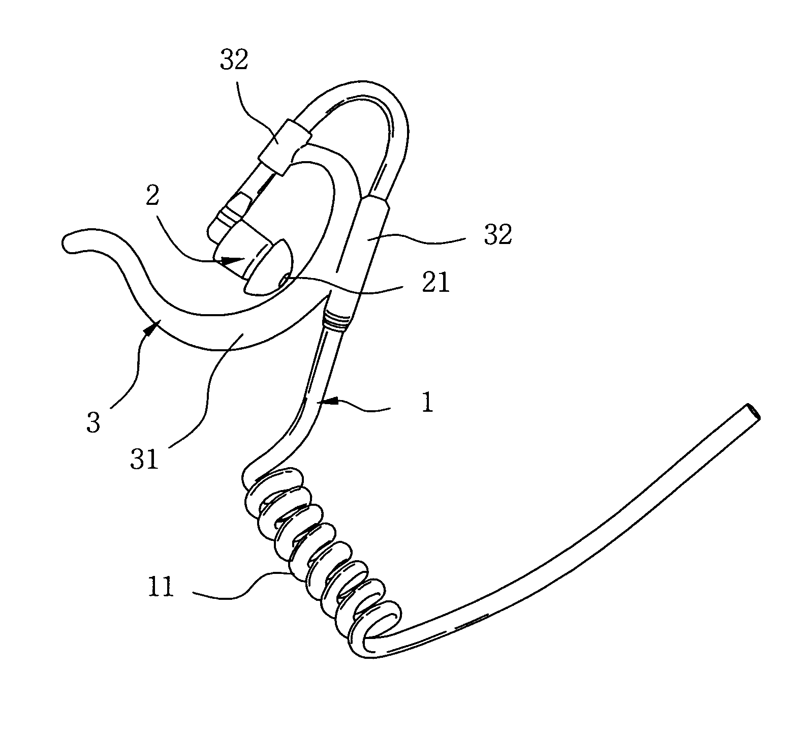
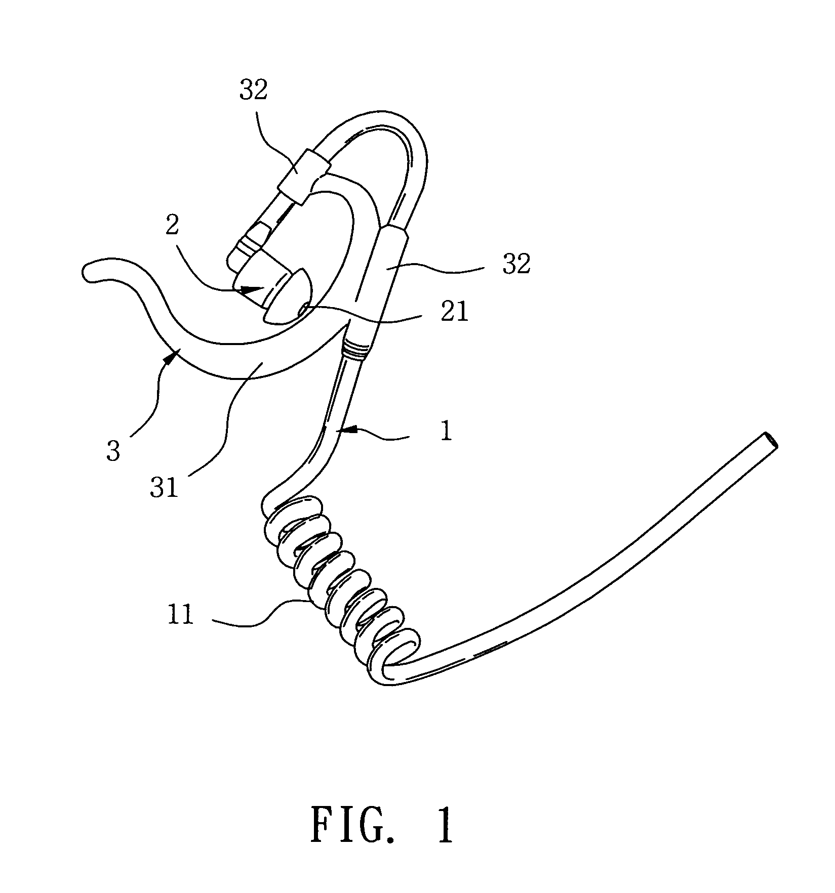
[0017]Referring to FIGS. 1 to 3, the present invention is used to connect an audio output device which is provided with a connector 4 for connecting an audio playing machine. An end of the connector 4 is extended with a leading wire 5, and a tail end of which is provided with a speaker 6. In addition, a positioning clip 7 is located on the leading wire 5 for clipping on a user, to facilitate carrying and using.

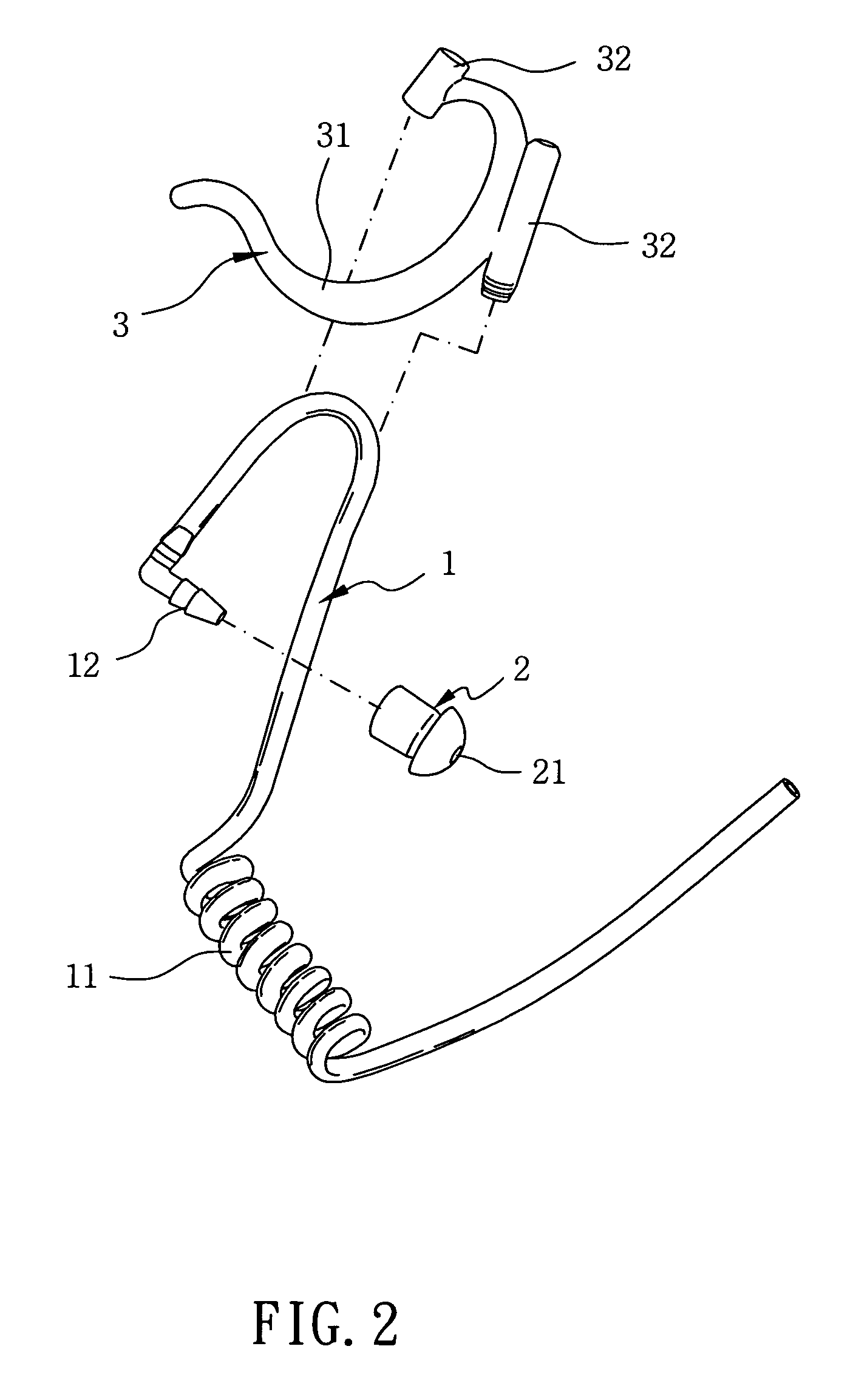
[0018]The present invention includes a sound tube 1, an earplug part 2, and an ear-hook part 3. The sound tube 1 is made by a soft tube material, an end of which is connected with the speaker 6, a middle section of which is provided with an elastic helical tube 11 to be extended elastically, and an outer rim at a tail end of which is formed with a tenon 12. The earplug part 2 is correspondingly sheathed with the aforementioned tenon 12 at the tail end of sound tube 1, and an interior of the earplug part 2 is provided with a through-hole 21 to connect with the sound tube 1. The...


PUM


Abstract

A microphone positioning structure is connected to an audio output device, and is composed of a sound tube, an end of which is connected with the audio output device; an earplug part which is located at a tail end of the aforementioned sound tube; an ear-hook part, an end of which is connected with the aforementioned sound tube. An end of the sound tube is plugged into the audio output device such as a trumpet or a loudspeaker, the ear-hook part is hung on a user's auricle for positioning, and the earplug part is inserted into the user's ear. In addition, while listening, the ear-hook part is hung and fixed on the user's auricle; therefore, the earplug part will not be subjected to a force, and it will not be fallen off due to a force of gravity and a shaking.

Description

BACKGROUND OF THE INVENTION[0001](a) Field of the Invention[0002]The present invention relates to a microphone positioning structure, and more particularly to a microphone positioning structure wherein a microphone can be hung on a user's auricle to prevent an earplug part from being easily fallen off or broken and separated at a connection place of a sound tube, due to an excessive stretching from a careless usage.[0003](b) Description of the Prior Art[0004]About 1700 years ago, an Italian scientist Torricelli brought up a concept that sound is propagating using air as a medium. Torricelli has thought using an experiment that a ring cannot be propagating in vacuum to prove his assertion. However, he could not accomplish his desire because the technique for creating the vacuum was not mature enough at that time. After that, a British physicist Boyle invented an air pump to create a vacuum to a container holding a bell, in order to carry out the experiment again; which has proven the...

Claims


Application Information

Patent Timeline
Patent Type & Authority Patents(United States)
IPC IPC(8): H04R9/08H04R25/00
CPCH04R1/1075H04R1/345H04R1/1016H04R1/105
Inventor CHEN, KUO-CHUNG
Owner JDI JING DENG IND CO LTD
Why Eureka
Try Eureka