Dual-control binding device

a binding device and dual-control technology, applied in the direction of ski bindings, sports apparatus, skiing, etc., can solve the problems of not being easily usable by another person, the binding system is particularly difficult to manipulate by its user, and the binding system is not sufficiently ergonomic, etc., to achieve the effect of low manufacturing cos

Inactive Publication Date: 2010-11-16
SALOMON SA
View PDF52 Cites 27 Cited by
  • Summary
  • Abstract
  • Description
  • Claims
  • Application Information

AI Technical Summary

Benefits of technology

[0020]As an alternative, the opening system can include a single control member that is manipulable according to the at least two distinct directions of manipulation, thus favoring simplicity, low manufacturing cost, and operating reliability of the device.

Problems solved by technology

For various reasons, due, especially, to size, weight and reliability considerations and to the necessity of not allowing an ill-timed opening of the binding device, opening systems are not always purely ergonomic or even substantially ergonomic in most situations, and are not sufficiently ergonomic in situations in which the user is placed.
Indeed, in the case of bindings adapted for use by children, the system can sometimes be rather child-friendly for the child using the binding device, but not easily usable by another person, for example an adult wanting to help the child unlock the binding system.
In other cases, the binding system can be particularly difficult to manipulate by its user when the user has fallen and is trying to release, whereas when used normally, the system gives complete satisfaction.

Method used


Image

  • Dual-control binding device
  • Dual-control binding device
  • Dual-control binding device

Examples


first embodiment

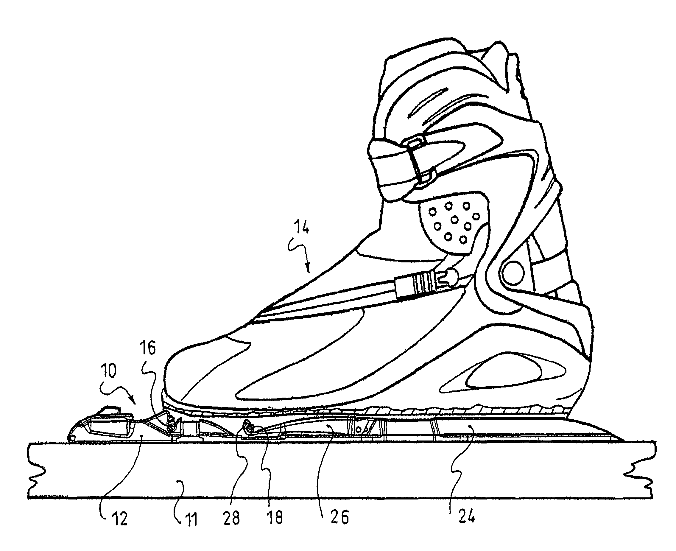
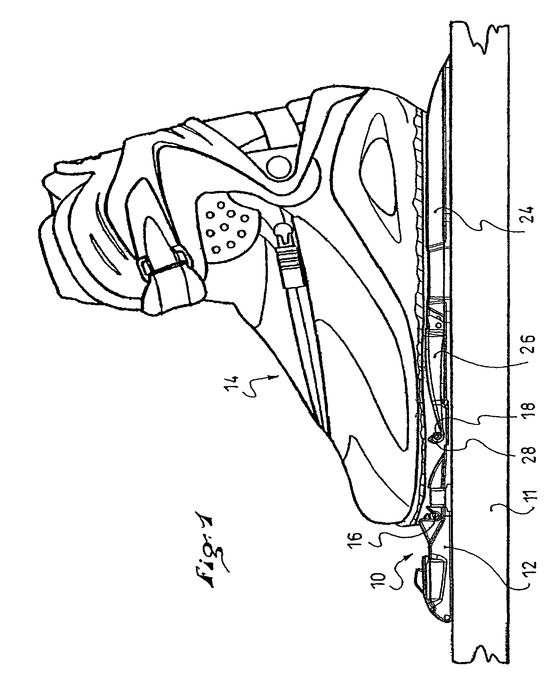
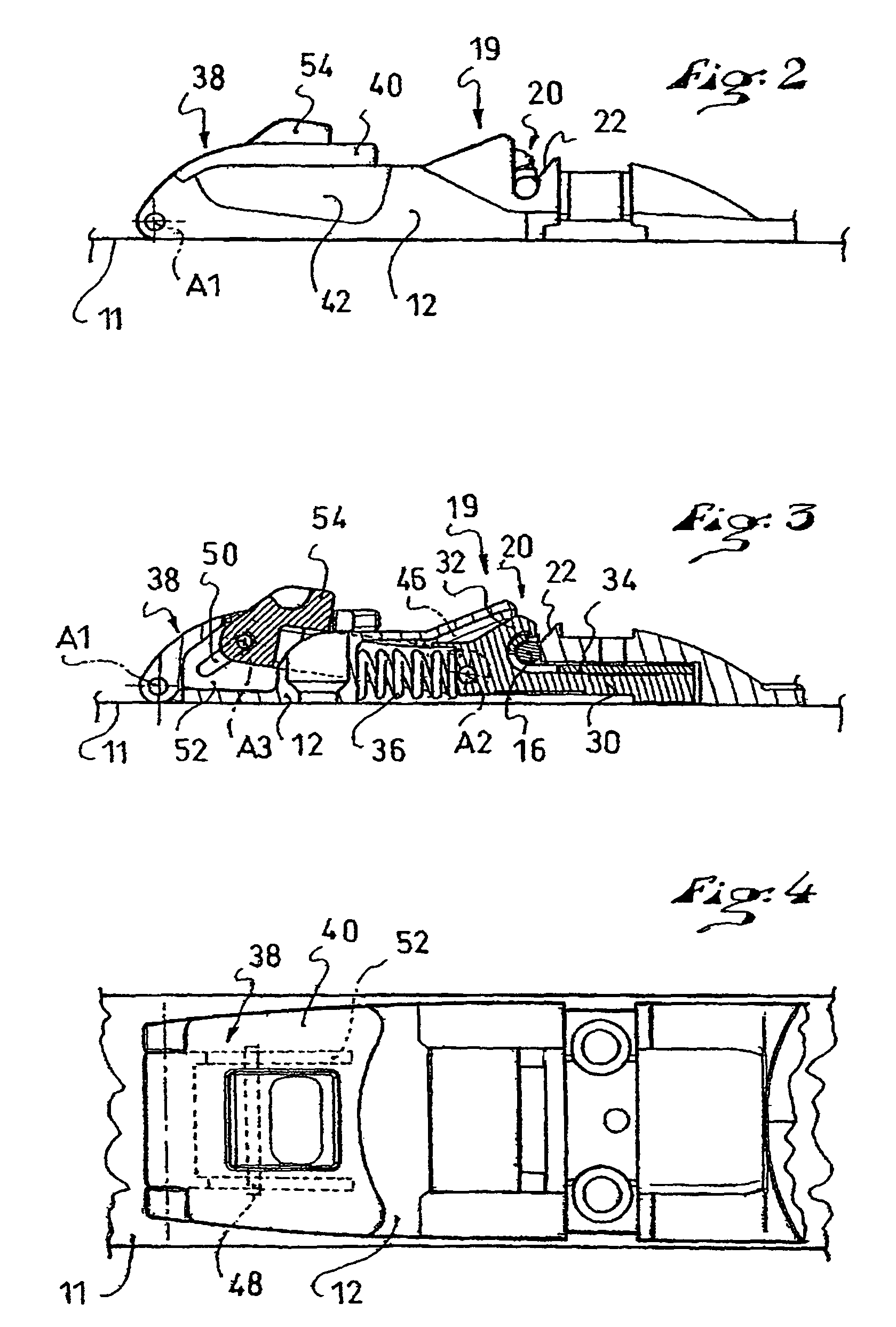
[0034]a binding 10 shown in FIGS. 1 to 6 includes a baseplate 12, or base, which is adapted to be fixed to a sports article 11, here a ski, but which could also be directly integrated or made in one-piece with the ski. The baseplate 12 could also be made of different parts, some or none of these parts possibly being integrated to the sports article / ski 11.

[0035]In the example shown, the device is adapted to carry out the binding of a boot 14 including connecting means in two parts. The boot includes two connecting pins 16, 18, which are arranged in the boot sole so as to be flush below the sole. Connecting pins 16, 18 of this type are described in the patent documents EP-913 102, EP-913 103, and U.S. Pat. No. 6,289,610, the disclosure of U.S. Pat. No. 6,289,610 being herein incorporated by reference thereto in its entirety for this purpose. Thus, in the particular embodiment being described here, the pins take the form of two cylindrical rods positioned within the sole but extending...

third embodiment

[0062]the invention is shown in FIGS. 10 to 12, in which the system for opening the locking mechanism includes only one control member. As illustrated in the drawings, the system is identical to the preceding one, except that the lever and the rocker are made as one and only piece: the rocker 78 articulated on the baseplate 12 about the axis A4, and which includes an upper support surface 68 arranged rearward from the axis A4, on the one hand, and front prehension arrangement (i.e., the member 76) arranged forward from the axis A4, on the other hand, and so as to trigger the same tipping move of the rocker 78, the user can choose to downwardly push on the rear surface 68, or to upwardly pull the front prehension member 76. In either case, the rocker revolves about the axis A4 and, by means of a control finger 72, controls the forward translation of the slide 30.

[0063]The fourth and fifth embodiments of the invention shown, respectively, in FIGS. 13-15 and in 16-18, also include a si...

fourth embodiment

[0065]In the fourth embodiment shown in FIGS. 13 to 15, the lever includes at its rear end a cam 92, which is arranged about the axis A5 and is adapted to be supported against the rear support surface 60 of the raised nose 58 arranged at the front of the slide 30. The eccentricity of the cam 92 is such that when the user triggers the lifting of the lever 80 by pulling its front end upwardly, the lever 80 then turns about the axis A5 of the connecting rod 82, the surface of the cam 92 pushes the slide 30 forwardly (c.f. FIG. 15). The lever 80 cannot translate rearwardly with respect to baseplate 12 because the connecting rod 82 is blocked toward the rear against the rear end of the slot 84. The movement of the lever is therefore a true rotation.

[0066]When the user pushes on the support surface 68 of the lever downwardly, the pin 88 tends to slide on the inclined surface 86 so as to trigger (by a cam effect) a forward translation of the lever 80. This translation is allowed since the ...


PUM


Abstract

A device for binding an article of footwear to a sports article, such as a binding for securing a boot to a cross-country ski, including a locking mechanism adapted to cooperate with a connecting member of the article of footwear, and including a user-manipulable opening system for controlling the opening of the mechanism, the opening system being directly or indirectly manipulable independently according to at least two distinct directions of manipulation for controlling the opening of the mechanism.

Description

CROSS-REFERENCE TO RELATED APPLICATION[0001]This application claims priority under 35 U.S.C. §119 of French Patent Application No. 05.02235, filed on Mar. 7, 2005, the disclosure of which is hereby incorporated by reference thereto in its entirety.BACKGROUND OF THE INVENTION[0002]1. Field of the Invention[0003]The invention relates to the field of devices for binding an article of footwear to a gliding apparatus.[0004]The invention is more particularly related to a device for binding an article of footwear to a gliding apparatus, such as a ski, snowshoe, ice skate, or roller skate, etc., and, more specifically, to a device for binding a cross-country ski boot to a corresponding ski.[0005]2. Description of Background and Relevant Information[0006]Bindings of the type to which the invention is directed, in every instance, include a locking mechanism adapted to cooperate with a connecting member of the article of footwear, and a user-manipulable system for controlling the opening mecha...

Claims


Application Information

Patent Timeline
Patent Type & Authority Patents(United States)
IPC IPC(8): A63C9/00A63C10/00A63C9/20A63C10/02
CPCA63C9/20
Inventor GIRARD, FRANCOISYELOVINA, EDDY
Owner SALOMON SA
Why Eureka
Try Eureka