Method and apparatus for a self-cleaning filter

a filter and self-cleaning technology, applied in the direction of auxillary pretreatment, mechanical details of gasifiers, separation processes, etc., can solve the problems of reducing performance, severe damage to components within the system, and reducing product quality, so as to reduce the dependence on external power sources in a gentle and efficient manner, and the effect of not involving or minimizing the dependence on external power sources

Inactive Publication Date: 2010-11-16
COMMUNITY POWER CORP
View PDF42 Cites 5 Cited by
  • Summary
  • Abstract
  • Description
  • Claims
  • Application Information

AI Technical Summary

Benefits of technology

[0008]Embodiments of the present invention provide techniques for removing filter cake from a filter media in a very gentle and efficient manner. Moreover, embodiments are well suited for use in rural areas, as well as in developing countries, and often do not involve or minimize dependence upon outside power sources. These approaches minimize the need for repair and maintenance of such ancillary equipment. In some embodiments, filters provide a large surface area available for filtering that increases and does not make contact with any solid surface during filtration, thus making all of the filter's surface area usable. Filter embodiments provided herein often require no bag supports, scrapers, brushes, or nozzles to dislodge the filter cake.

Problems solved by technology

If not separated, the particulate matter may degrade product quality, efficiency, reduce performance, or even cause severe damage to components within the system.
However, the particulate material often becomes entrapped in the filter element.
Manual cleaning is a time consuming operation as it involves significant disassembly and re-assembly.
Manual cleaning can also be a dirty one, with the potential for dislodging hazardous, or toxic, particles that can be inhaled or ingested.
It can also be a dangerous operation, if the fluid is flammable or toxic.
However, filters that use back pulsing to dislodge materials or blades to scrape off caked particulate are often very intricate and costly mechanisms.
Some filters are cleaned with sprayed fluids, such as water or air to remove the particulates often resulting in the need to dispose of a large fluid volume of contaminated, hazardous matter.
Moreover, many current approaches require extreme pressures or forces to dislodge caked particulate from the filter.

Method used


Image

  • Method and apparatus for a self-cleaning filter
  • Method and apparatus for a self-cleaning filter
  • Method and apparatus for a self-cleaning filter

Examples


Embodiment Construction

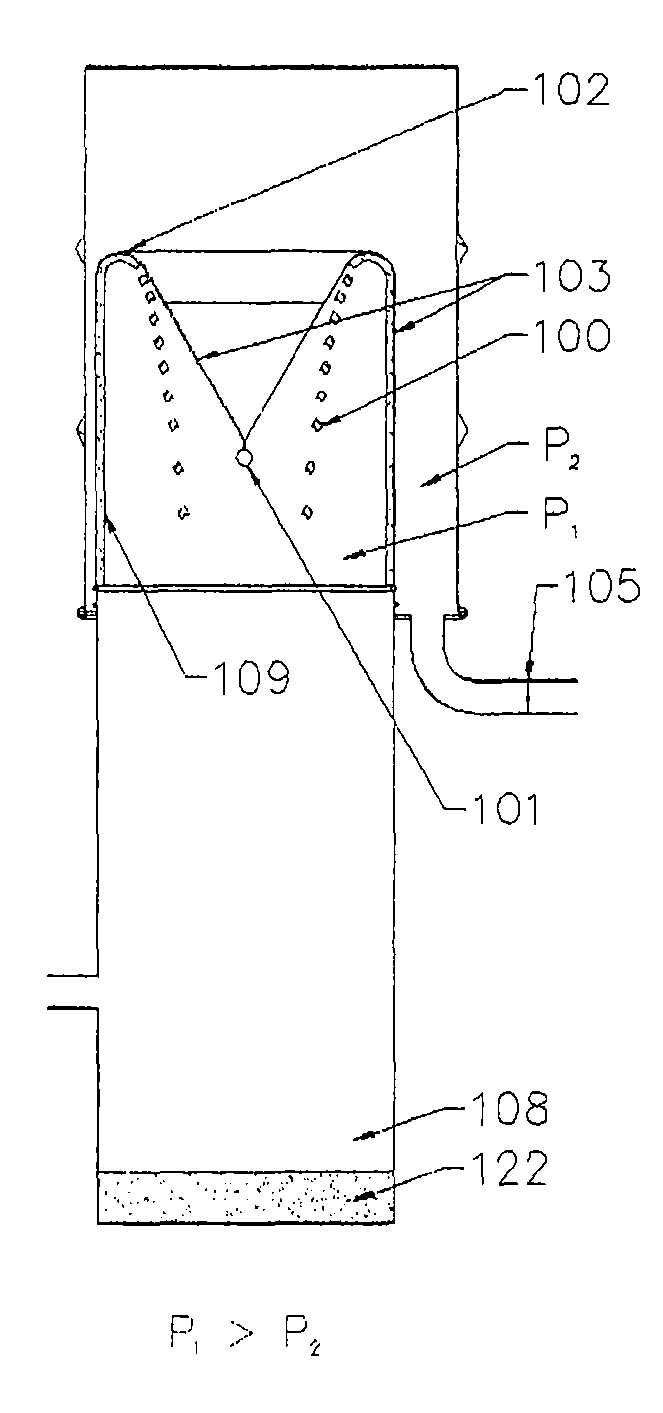
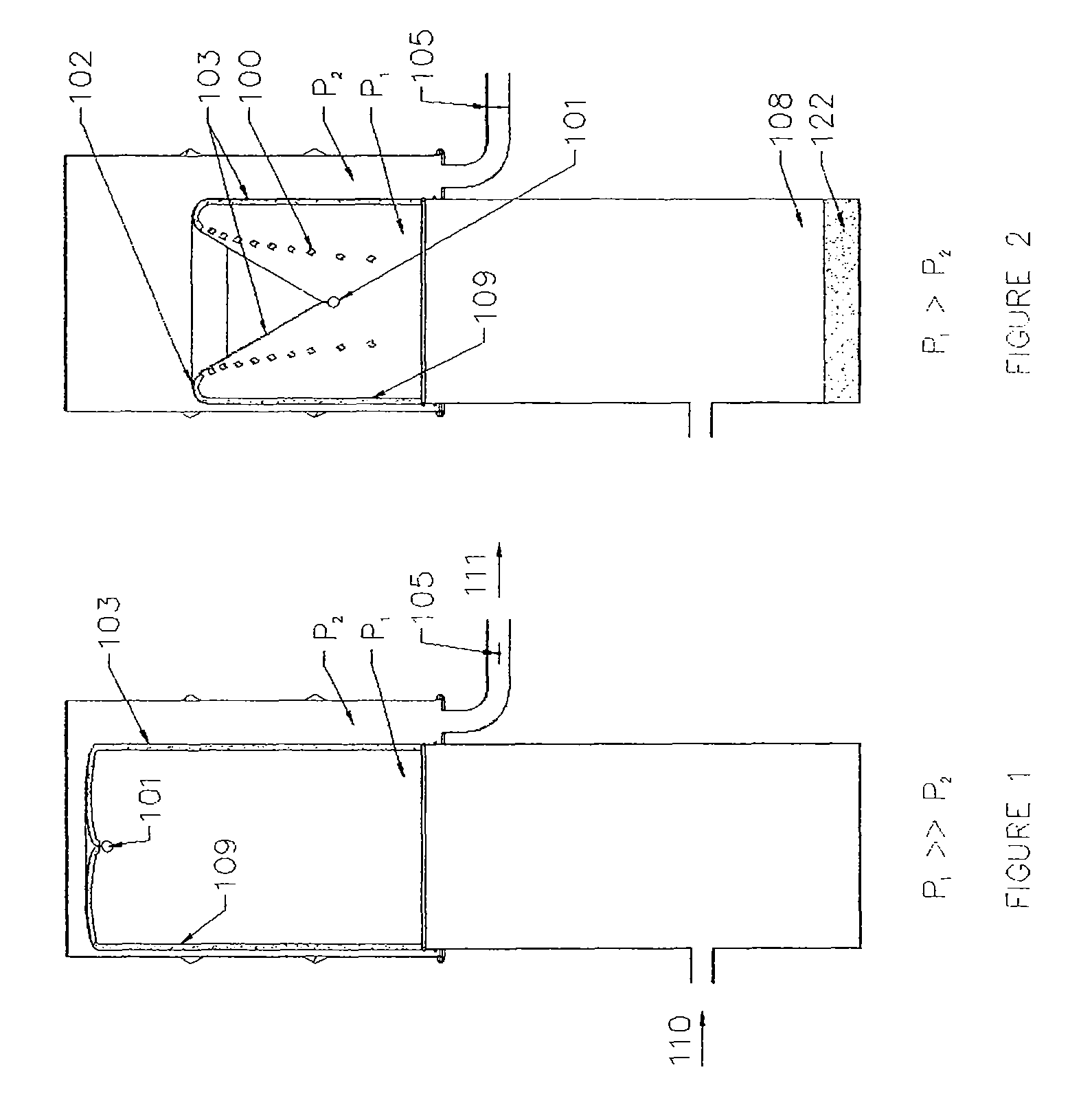
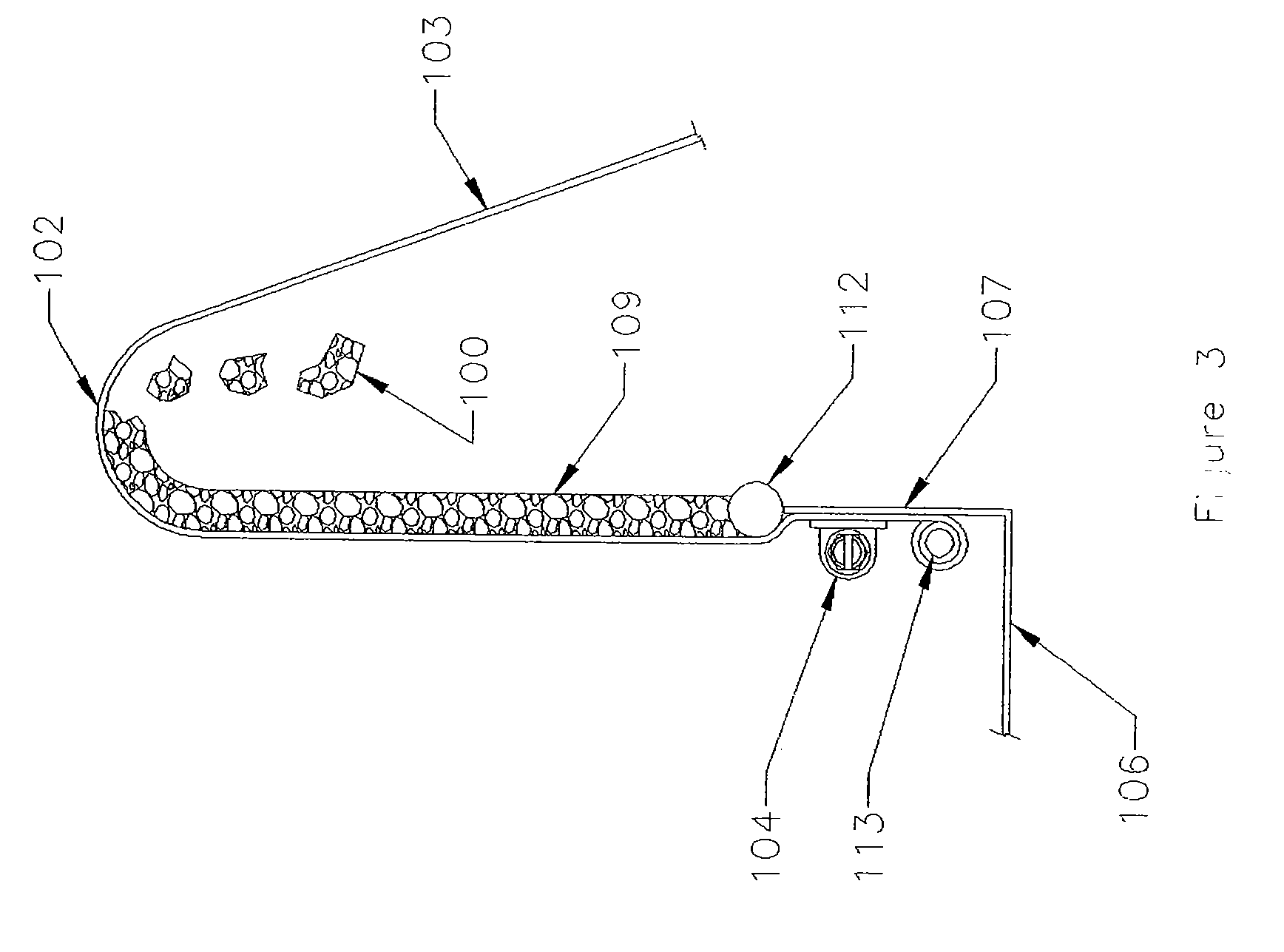
[0023]Embodiments of the present invention encompass systems and methods that allow an inflated filter to slowly deflate and to gently turn itself inside out after the flow of fluid is significantly reduced or eliminated completely.

[0024]Some current filter techniques rely upon water scrubbing to remove residual fine particles from fluids such as hot gases. Typically, the water used for scrubbing is in the form of a mist. Unfortunately, these scrubbing mists can be themselves difficult to remove from the fluid stream. The use of water scrubbing may also create a waste-water disposal problem. Coalescing filters are often used to remove these fine materials and mists by Brownian motion, but can introduce a significant, undesirable pressure drop to the system. In some cases the captured particles may not be washed off the coalescing filter by the captured mists, and the coalescing filters may require periodic service to remove the captured particles, or the coalescing filters may need ...


PUM


Abstract

A method and apparatus for removing fine particulate matter from a fluid stream without interrupting the overall process or flow. The flowing fluid inflates and expands the flexible filter, and particulate is deposited on the filter media while clean fluid is permitted to pass through the filter. This filter is cleaned when the fluid flow is stopped, the filter collapses, and a force is applied to distort the flexible filter media to dislodge the built-up filter cake. The dislodged filter cake falls to a location that allows undisrupted flow of the fluid after flow is restored. The shed particulate is removed to a bin for periodic collection. A plurality of filter cells can operate independently or in concert, in parallel, or in series to permit cleaning the filters without shutting off the overall fluid flow. The self-cleaning filter is low cost, has low power consumption, and exhibits low differential pressures.

Description

STATEMENT AS TO RIGHTS TO INVENTIONS MADE UNDER FEDERALLY SPONSORED RESEARCH OR DEVELOPMENT[0001]The U.S. Government has a paid-up license in this invention and the right in limited circumstances to require the patent owner to license others on reasonable terms as provided for by the terms of SBIR Contract No. DE-FG02-03ER83630 and SMB Contract No. ZDH-9-29047-01, both awarded by the U.S. Department of Energy.CROSS-REFERENCES TO RELATED APPLICATIONS[0002]This application claims the benefit of U.S. Provisional Application No. 60 / 694,156, filed Jun. 28, 2005. This application is also related to U.S. patent application Ser. No. 11 / 427,231, filed Jun. 28, 2006. The entire contents of each of these applications are incorporated herein by reference.BACKGROUND OF THE INVENTION[0003]Embodiments of the present invention relate to a filter apparatus and method, and more particularly to self-cleaning filters for removing relatively fine particulate material from a fluid stream.[0004]Many fluid...

Claims


Application Information

Patent Timeline
Patent Type & Authority Patents(United States)
IPC IPC(8): B01D46/00
CPCB01D29/27B01D46/0072B01D46/0095C10J3/20C10J3/26C10J3/30C10J3/40C10J3/66C10J3/723B01D29/70C10J2300/0956C10J2200/09C10J2300/0903C10J2300/0916C10J2300/092C10J2300/0946C10J2200/152B01D46/74
Inventor DIEBOLD, JAMES P.LILLEY, ARTHURBROWNE, III, KINGSBURYWALT, ROBB RAYDUNCAN, DUSTINWALKER, MICHAELSTEELE, JOHNFIELDS, MICHAEL
Owner COMMUNITY POWER CORP
Why Eureka
Try Eureka