Supercharge Your Innovation With Domain-Expert AI Agents!

Optical architecture having a rotating polygon for use in imaging systems

a technology of optical architecture and rotating polygon, which is applied in the field of optical devices and optical architectures employing reflective or refractive polygons, can solve the problems of difficult to generate a far-field illumination area with uniform illumination intensity, and difficult to optically couple solid-state illuminators with light valves

Active Publication Date: 2010-11-16
TEXAS INSTR INC
View PDF11 Cites 3 Cited by
  • Summary
  • Abstract
  • Description
  • Claims
  • Application Information

AI Technical Summary

Benefits of technology

The optical architecture enables simultaneous illumination of different colors on the light valve with uniform intensity distribution, improving the efficiency and brightness of images produced in display systems by effectively handling the collimated light from solid-state illuminators.

Problems solved by technology

Regardless of the widely embraced superior properties of solid-state illuminators over traditional light sources, it is however difficult to optically couple solid-state illuminators with light valves.
For example, it is difficult to generate a far-field illumination area with uniform illumination intensity at the light valve location using solid-state or narrow-banded light illuminators because the illumination light from the solid-state illuminators and most narrow-banded illuminators are highly collimated as compared to the light from traditional illuminators.

Method used


Image

  • Optical architecture having a rotating polygon for use in imaging systems
  • Optical architecture having a rotating polygon for use in imaging systems
  • Optical architecture having a rotating polygon for use in imaging systems

Examples


Embodiment Construction

[0040]In the following, the optical system / architecture and imaging systems using the same will be discussed with selected examples wherein the imaging system is a display system that employs a light valve having an array of individually addressable pixels. However, it will be appreciated by those skilled in the art that the following discussion is for demonstration purpose, and should not be interpreted as a limitation. Other variations within the scope of this disclosure are also applicable. For example, other imaging systems, such as systems for storing information of image (e.g. 2D images or holographic images) in image storing mediums are also applicable.

Display Systems with Beam-Scanning Mechanisms

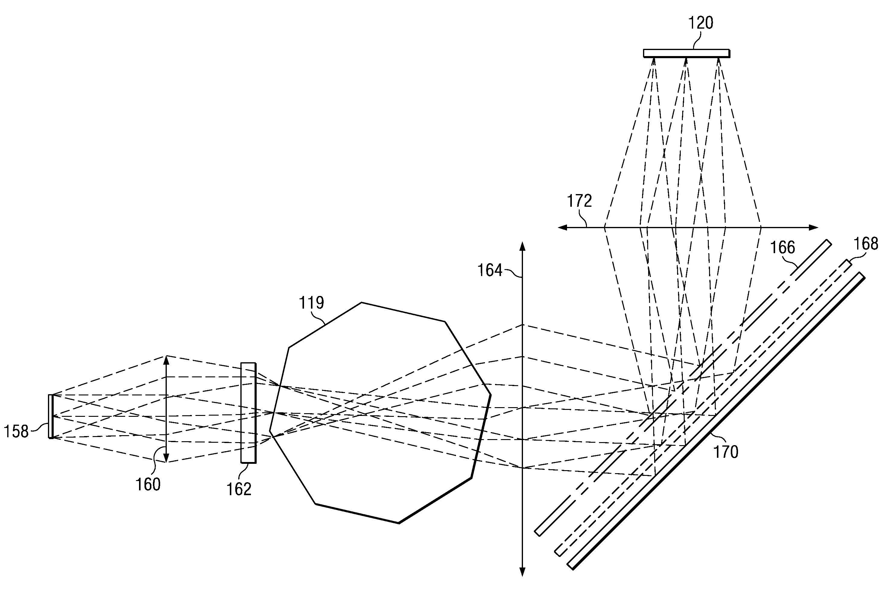
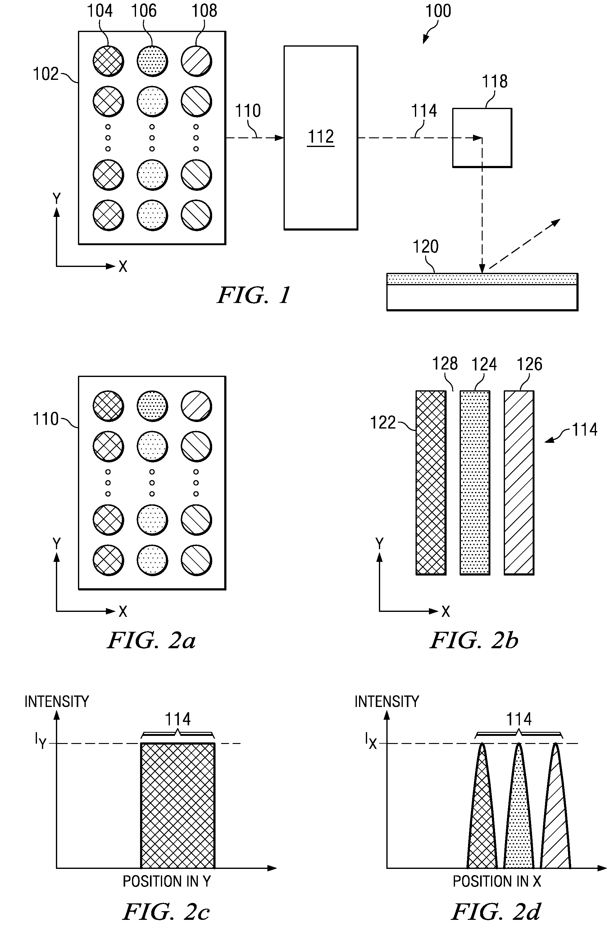
[0041]Referring to the drawings, FIG. 1 schematically illustrates an exemplary display system in which examples of this disclosure can be implemented. In this example, display system 100 comprises illuminator unit 102 providing light 110. Light 110 is directed to scanning unit 118. T...


PUM


Abstract

An optical architecture comprises a refractive cylinder that is movable relative to the incident light. By moving the refractive cylinder, the output light from the refractive cylinder is capable of sweeping through a spatial angle. Examples of the optical architecture can be implemented in an imaging system, such as a display system, for sequentially illuminating the target, such as a light valve in a display system with a high brightness.

Description

CROSS-REFERENCE TO RELATED CASES[0001]This U.S. patent application claims priority from U.S. provisional patent application Ser. No. 60 / 947,618 to Destain, filed Jul. 2, 2007, the subject matter being incorporated herein by reference in its entirety.[0002]This U.S. patent application is related to U.S. patent application “An Optical Structure and an Imaging System Using the Same,” 11 / 856,010 and “An Optical Architecture”, 11 / 856,004, both to Grasser and filed on the same day as this application; the subject matter of each being incorporated herein by reference in its entirety.TECHNICAL FIELD OF THE DISCLOSURE[0003]The technical field of this disclosure relates to the art of optical devices and architectures and more particularly to the art of optical devices and optical architectures employing reflective or refractive polygon for use in imaging systems.BACKGROUND OF THE DISCLOSURE[0004]In recent years, solid-state light illuminators, such as LASERs and light-emitting-diodes (LEDs), ...

Claims


Application Information

Patent Timeline
Patent Type & Authority Patents(United States)
IPC IPC(8): G02B26/08
CPCG02B26/12G03B21/10H04N9/3129H04N9/3164G02B13/22
Inventor DESTAIN, PATRICK RENESMITH, STEVEN EDWARD
Owner TEXAS INSTR INC
Features
  • R&D
  • Intellectual Property
  • Life Sciences
  • Materials
  • Tech Scout
  • Unparalleled Data Quality
  • Higher Quality Content
  • 60% Fewer Hallucinations
Learn More