

Gradation correction method and device
a technology of gradation correction and video signal, which is applied in the field of gradation conversion of video signal, can solve the problems of deteriorating image quality, affecting image quality, and being able to reprodu
- Summary
- Abstract
- Description
- Claims
- Application Information
AI Technical Summary
Problems solved by technology
Method used
Image

Examples
first embodiment
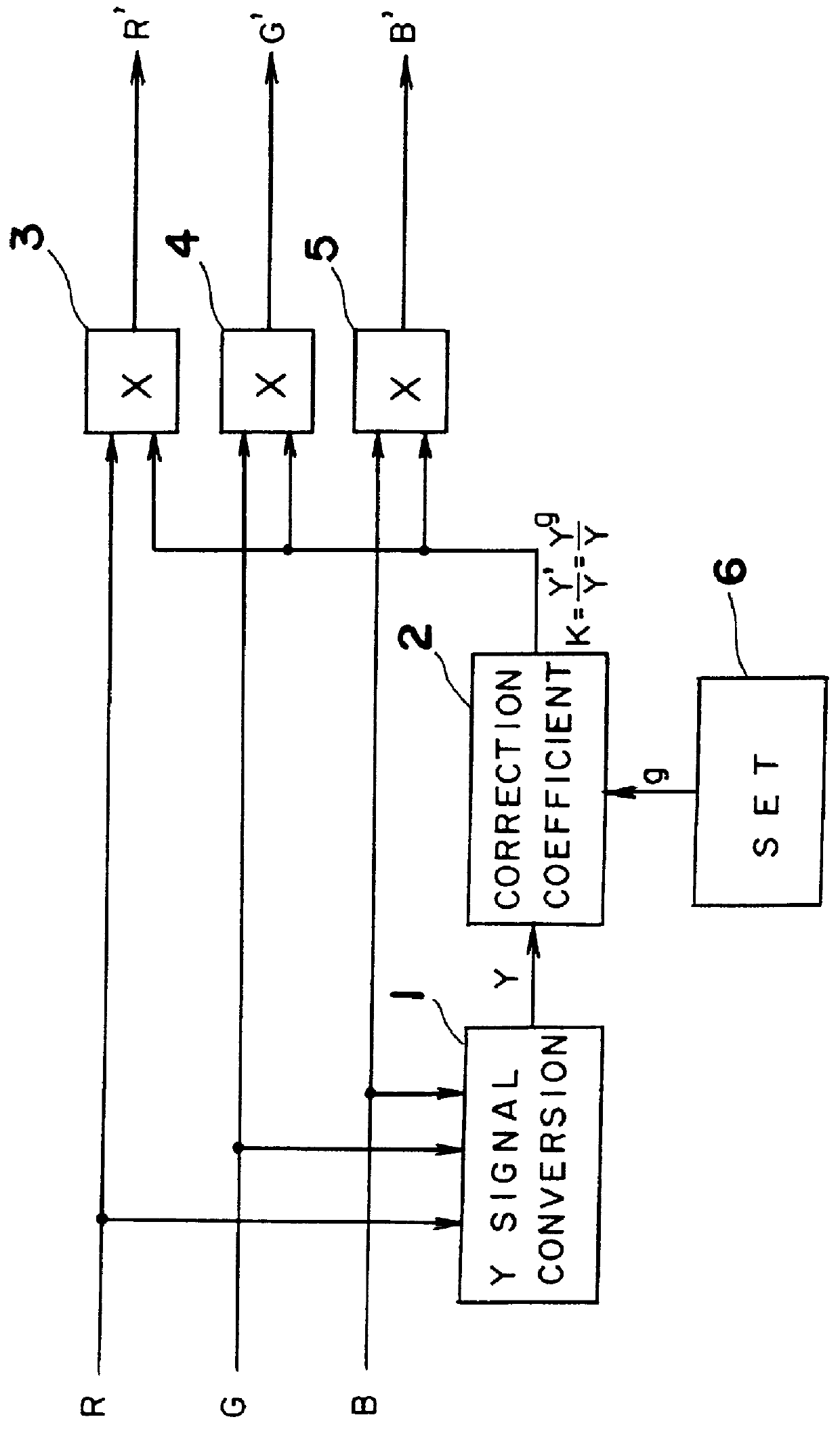
The operation of the gradation correction device according to the present invention is described next.
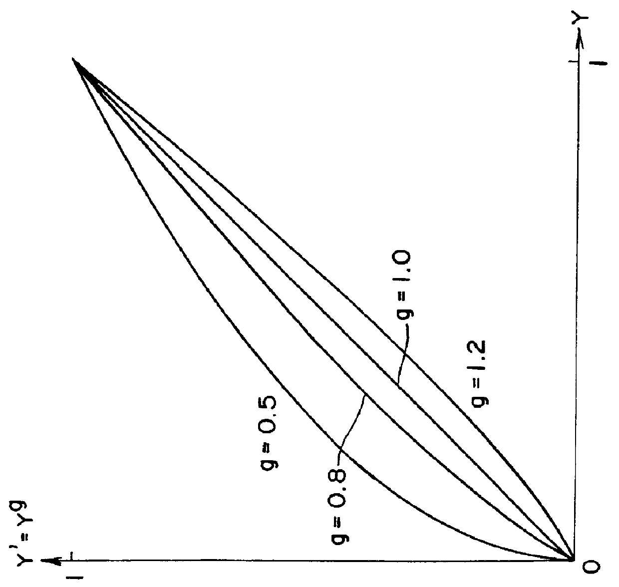
In this example it is assumed that the value g for gradation conversion is 0.75 to brighten the intermediate tones of the image. It is further assumed that the input colors are R=0.3, G=0.4, and B=0.5, and that the luminance component of the input signal is therefore Y=0.381 from equation 1. Thus, from the equation 6, the luminance component f(Y) is:
f(Y)=Y'=Y.sup.g =0.381.sup.0.75 =0.4849482.
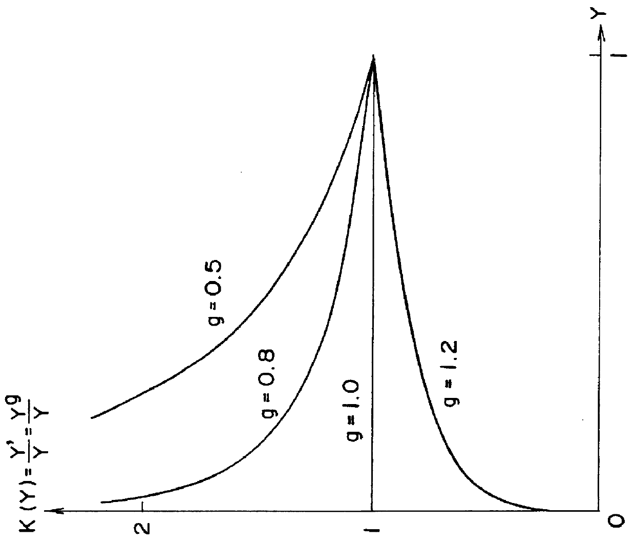
Furthermore, from equation 9,
K(Y)=Y' / Y=0.4849482 / 0.381=1.27283
is obtained, so that the correction value K is determined to be K=1.27283, and the values of the corrected output signal are R'=0.38185, G'=0.50913, and B'=0.63641 from equations 2, 3, and 4, respectively.
Since the R':G':B' ratio is 3:4:5, there is thus no change in the input and output signal ratios. It follows that the brightness of intermediate tone levels can be controlled without changing the hue and saturation, and when R=G=B=0 ...
second embodiment
The operation of the gradation correction device according to the present invention is described next.
In this example it is assumed that the value g for gradation conversion is 0.75 to brighten the intermediate tones of the image. It is further assumed that the input colors are R=0.3, G=0.4, and B=0.5, and that the luminance component of the input signal is therefore Y=0.381 from equation 1. Furthermore, similar to the above, the luminance component f(Y) is:
f(Y)=Y'=Y.sup.g =0.381.sup.0.75 =0.4849482.
Thus, from equations 10, 11, and 12, respectively,
R'=f(Y)*R / Y=0.4849482.times.0.3.div.0.381=0.381185 (10)
G'=f(Y)*G / Y=0.4849482.times.0.4.div.0.381=0.50913 (11)
B'=f(Y)*B / Y=0.4849482.times.0.5.div.0.381=0.63641 (12)
are obtained.
Since the R':G':B' ratio is 3:4:5, there is thus no change in the input and output signal ratios. Thus, the brightness of intermediate tone levels can be controlled without changing the hue and saturation.
A characteristic of this embodiment is the high effective pre...
third embodiment
The operation of the gradation correction device according to the present invention is described next.
In this example it is assumed that the value g for gradation conversion is 0.75 to brighten the intermediate tones of the image. It is further assumed that the input signal values are Y=0.4, B-Y=-0.2, and R-Y=0.2, and thus, the R, G, and B components of the input signal are R=0.6, G=0.3356, and B=0.2 from equation 1. Thus, the output signal values of the gradation correction device
Y'=Y.sup.g =0.4.sup.0.75 =0.503
B'-Y'=-0.2.times.0.503.div.0.4=-0.2515
R'-Y'=0.2.times.0.503 .div.0.4 =0.2515
are obtained from equations 14, 15, and 16. Furthermore, since the R, G, and B components of the output signal are R'=0.7545, G'=0.422, and B'=0.2515, there is thus no change in the input and output signal ratios. The brightness of intermediate tone levels can thus be controlled without changing the hue and saturation.
Another alternative embodiment of a gradation correction device according to the pre...
PUM
| Property | Measurement | Unit |
|---|---|---|
| luminance | aaaaa | aaaaa |
| brightness | aaaaa | aaaaa |
| colors | aaaaa | aaaaa |
Abstract
Description
Claims
Application Information