Light source apparatus, display apparatus, terminal apparatus, and control method thereof

a terminal and light source technology, applied in the direction of instruments, static indicating devices, etc., can solve the problems of difficult reduction of detectors and controllers, inferior contrast and other aspects of display performance, and the above-described conventional display apparatuses equipped with a light source control device. , to achieve the effect of less expensive and small correction of hue changes

Active Publication Date: 2007-09-13
NEC LCD TECH CORP
View PDF6 Cites 100 Cited by
  • Summary
  • Abstract
  • Description
  • Claims
  • Application Information

AI Technical Summary

Benefits of technology

[0019] An object present invention is to provide a light source apparatus capable of correcting changes in hue, whereby costs can be lowered and the light source apparatus can be reduced in size; to provide a display apparatus equipped with this light source apparatus and capable of correcting the hue of a display; to provide a terminal apparatus equipped with this display apparatus; and to provide a method for controlling these apparatuses.

Problems solved by technology

Energy consumption can be reduced in the reflective type, since it can utilize external light in the display apparatus and there is no need to provide the display apparatus with a light source, but contrast and other aspects of display performance are inferior compared to the transmissive type.
However, the above-described conventional display apparatuses equipped with a light source control device are subject to the following problems.
Specifically, in the first conventional display apparatus equipped with a light source control device, a minimum of three light detectors or light sensors are needed for the colors red, green, and blue, and it is therefore difficult to reduce the size of the detectors and controllers, and it is also difficult to lower costs.
Not only is it difficult to reduce size owing to these connections, but reliability is also reduced, and it is difficult to lower costs.
Furthermore, since three light sensors correspond to the colors red, green, and blue, separate wavelength filters are needed and it is difficult to lower costs any further.

Method used


Image

  • Light source apparatus, display apparatus, terminal apparatus, and control method thereof
  • Light source apparatus, display apparatus, terminal apparatus, and control method thereof
  • Light source apparatus, display apparatus, terminal apparatus, and control method thereof

Examples


first embodiment

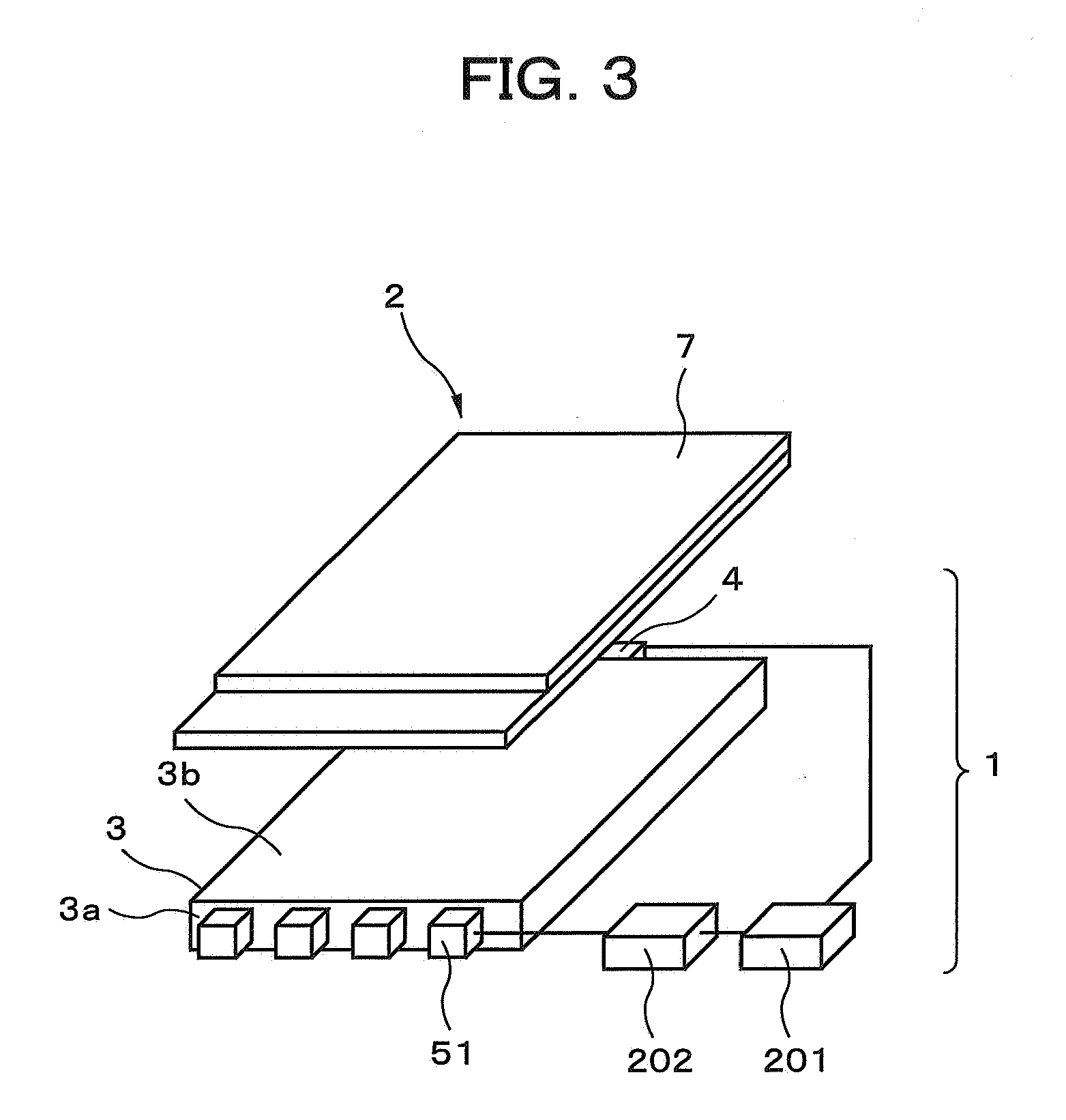
[0115] The light source apparatus, display apparatus, terminal apparatus, and method for controlling these apparatuses according to embodiments of the present invention are described in detail below with reference to the attached diagrams. The light source apparatus, display apparatus, terminal apparatus, and method for controlling these apparatuses according to the present invention will first be described. FIG. 3 is a perspective view showing a display apparatus according to the present embodiment, and FIG. 4 is a perspective view showing a terminal apparatus according to the present embodiment.

[0116] As shown in FIG. 3, a display apparatus 2 according to the first embodiment is composed of a light source apparatus 1 and a transmissive liquid crystal display panel 7. The light source apparatus 1 is provided with a light guide plate 3 composed of a transparent material. The light guide plate 3 is in the shape of a rectangular plate. Light sources 51 are disposed at a position facin...

ninth embodiment

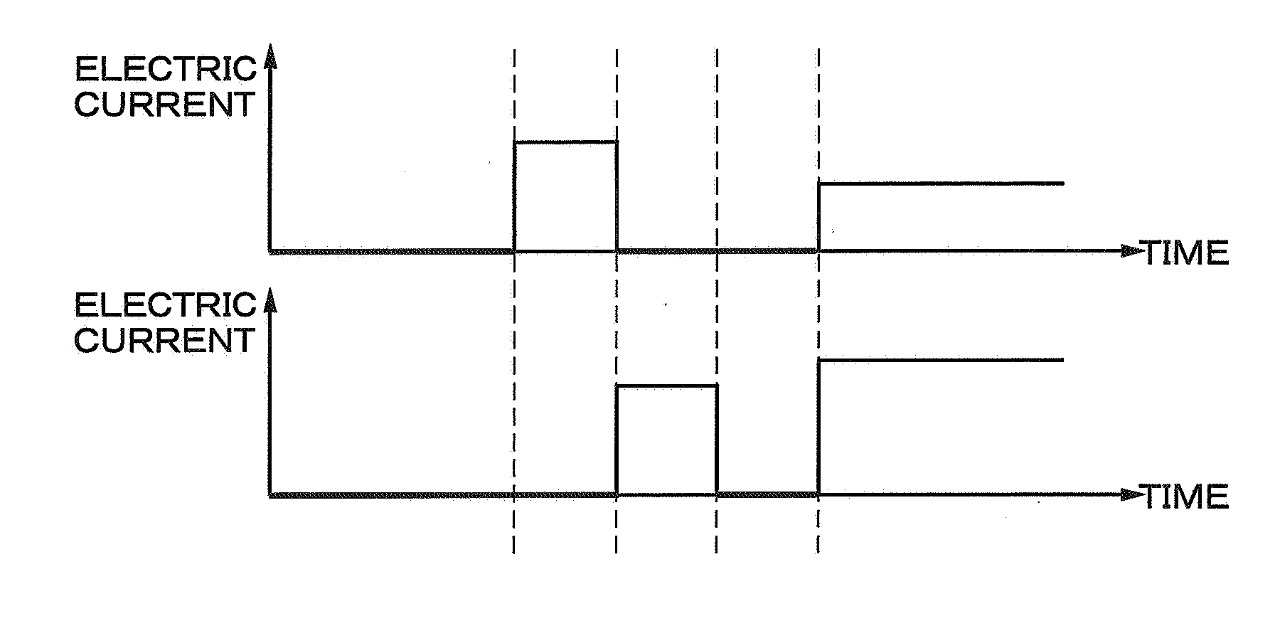
[0198] In the ninth embodiment, the light source apparatus is off prior to time t1, and the RGB-LED is turned off, as shown in FIG. 18. As a result, the output result of the light sensor is also substantially 0, as shown in FIGS. 18G and 18H. The light source is turned on at time t1. Specifically, when the control circuit 201 receives a command to change to an on state, the control circuit 201 simultaneously turns on the red and green light-emitting elements of the RBG-LED 51, as shown in FIGS. 18A to 18C. This time period is the time period from t1 to t2, and the initial value of the electric current is set in advance in the control circuit 201. This prescribed electric current flows to the red and green light-emitting elements, whereby the red and green light-emitting elements are turned on, as shown in FIGS. 18D to 18F. The red light sensor 42 receives the light of the red light-emitting element, as shown in FIG. 18G, and the results are outputted to the control circuit 201. The ...

tenth embodiment

[0205] In the tenth embodiment, the light source apparatus is off prior to time t1, and the BYB-LED is turned off, as shown in FIG. 20. As a result, the output result of the light sensor is also substantially 0, as shown in FIG. 20E. The control circuit 201 turns on the white BY-LED 52a when the light source is turned on at time t1, as shown in FIGS. 20A and 20B. This time period is from t1 to t2, and the initial value of the electric current is set in advance in the control circuit 201. This prescribed electric current flows to the white BY-LED 52a, whereby the white BY-LED 52a is turned on, as shown in FIGS. 20C to 20D. The light sensor 4 receives the light of the white BY-LED 52a, as shown in FIG. 20E, and the results are outputted to the control circuit 201. The broken line shows the reference data of the light sensor 4 set in advance in the control circuit 201, i.e., the data indicating that the light sensor 4 should output when the white BY-LED 52a is lighted at an ideal inten...


PUM


Abstract

A light source apparatus has two or more light sources that have different light-emission spectra and that can be controlled independently, and also has light sensors for detecting the quantity of light emitted by the light sources. The light sensors are composed of one type of light sensor that is not provided with a color filter for selecting the wavelength of received light, and the light sensors are sensitive to wavelength ranges that are sufficiently broad to simultaneously receive light in red, green, and blue wavelength ranges. A control circuit controls the two or more light sources to emit light in a time sequential fashion, and compares reference data with the output values of the light sensors to control the quantity of light emitted by the light sources by means of a light source drive circuit. It is thereby possible to reduce the cost and size of a light source apparatus that is capable of correcting changes in hue.

Description

BACKGROUND OF THE INVENTION [0001] 1. Field of the Invention [0002] The present invention relates to a light source apparatus capable of correcting changes in hue, to a display apparatus provided with this light source apparatus and capable of correcting the hue of a display, to a terminal apparatus equipped with this display apparatus, and to a method for controlling these apparatuses. [0003] 2. Description of the Related Art [0004] Because of their thin profile, light weight, small size, low energy consumption, and other advantages, display apparatuses that use liquid crystals have been widely deployed and used in a range of devices that includes monitors, televisions (TV: Television), and other large terminal apparatuses; notebook-type personal computers, cash dispensers, vending machines, and other mid-sized terminal apparatuses; and personal TVs, PDAs (Personal Digital Assistance: personal information terminal), mobile telephones, mobile gaming devices, and other small terminal...

Claims


Application Information

Patent Timeline
Patent Type & Authority Applications(United States)
IPC IPC(8): G09G3/36
CPCG09G3/3413G09G2320/0666G09G2320/0633G09G2310/0235
Inventor UEHARA, SHIN-ICHIIMAI, MASAO
Owner NEC LCD TECH CORP
Why Eureka
Try Eureka