Interpositional biarticular disk implant

a technology implant, which is applied in the field of interpositional biarticular disk implant, can solve the problems of loss of stability, insufficient overall stability of such an implant shape, and less than satisfactory, and achieve the effect of stabilizing the implan

Active Publication Date: 2010-11-23
ASCENSION ORTHOPEDICS
View PDF19 Cites 27 Cited by
  • Summary
  • Abstract
  • Description
  • Claims
  • Application Information

AI Technical Summary

Benefits of technology

[0003]The invention provides a one component implant having biconvex articular surfaces which respectively bear against appropriately resected facing surfaces of the base of the metacarpus and the carpal bone segment, e.g. the trapezium, or between the articular surfaces which form the corresponding joints of the foot. This biconvex design allows for both flexion-extension joint motion and abduction-adduction joint motion. A hole is provided that extends through the implant at the axis of symmetry and smoothly flairs into each of the convex articular surfaces; it provides a means of stabilizing the implant against potential dislocation by passing a flexible cord or harvested tendon through this central hole in the implant.
[0005]In another particular aspect, the invention provides a surgically implantable bone prosthesis designed to replace a CMC or TMT joint, which implant comprises: a disk having a pair of convex surfaces and an axial, flaring opening which extends therethrough from convex surface to convex surface to accommodate a flexible cord that is passed through passageways created in the proximal bone of the digitus and in the trapezium or other carpal or tarsal bone, which disk once surgically implanted allows said proximal bone to flex relative to said other bone enough for useful hand or foot function, with each bone sliding on the respective mating convex surface of the disk while the flexible cord conforms to the flaring surface of the axial hole in the plane of flexion.

Problems solved by technology

In a case of fracture or severe arthritic pain at the base of the thumb, there has been some tendency to remove the arthritic articular surfaces of the joint between the trapezium and this metacarpus (which is referred to as the CMC joint) or to remove the entire trapezium; however, when this occurs, stability is lost.
Hand Surg 11A:324-32 (1986), however, the results are felt to be less than satisfactory.
However, in the region of the CMC joint, it is felt that the resultant overall stability of such an implant shape is insufficient for patient satisfaction.

Method used


Image

  • Interpositional biarticular disk implant
  • Interpositional biarticular disk implant
  • Interpositional biarticular disk implant

Examples


Embodiment Construction

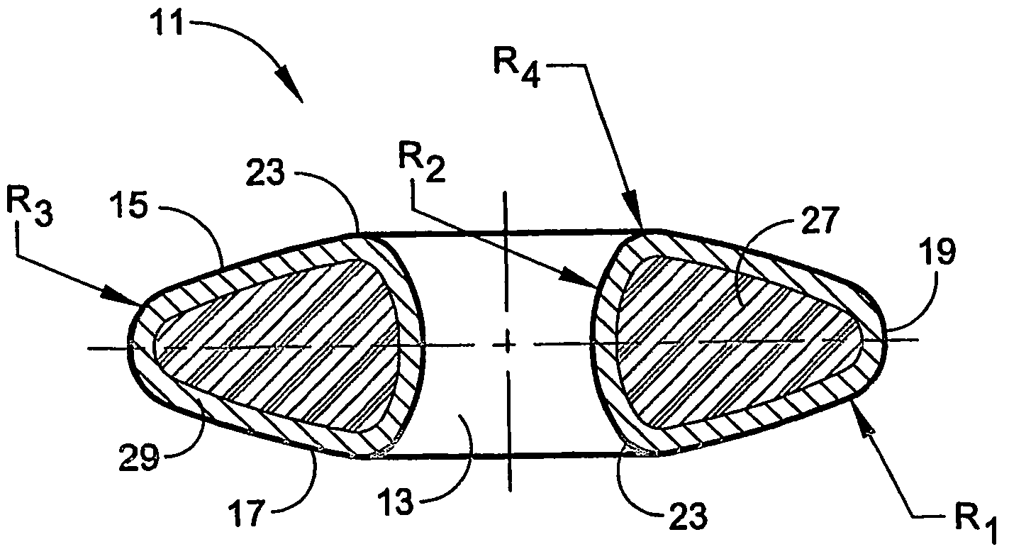
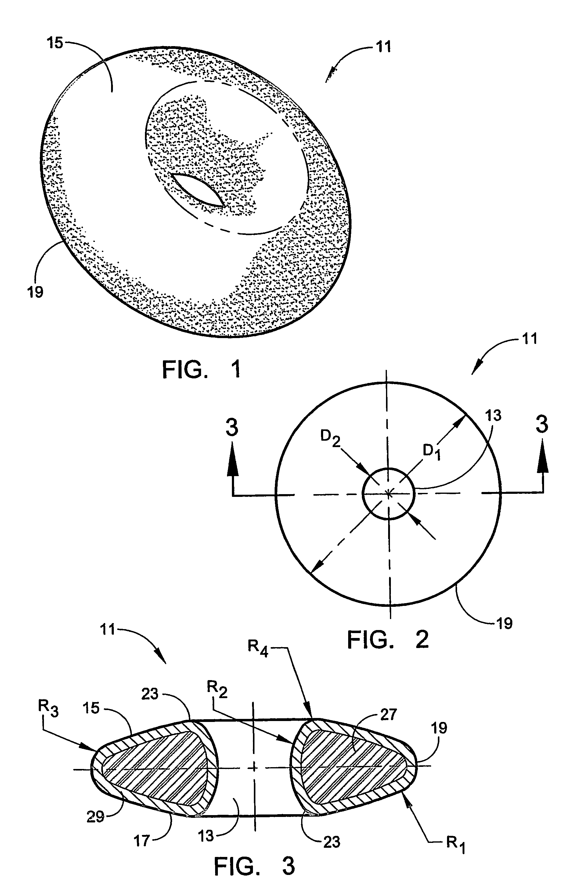
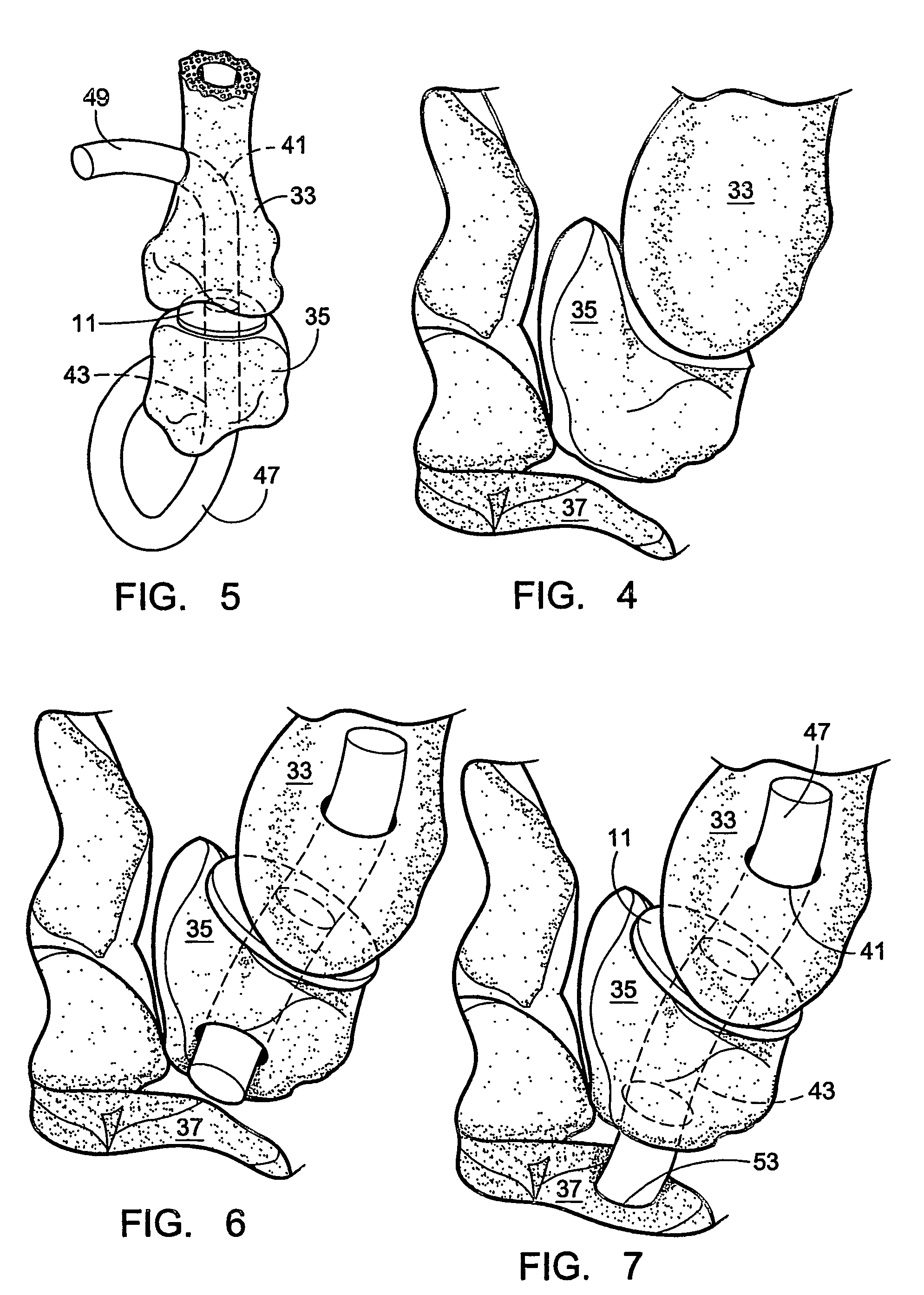
[0014]The invention provides an integral disk implant of 11 a biconvex shape that is designed to provide a stable CMC joint between resected surfaces of the base of the metacarpus of the thumb and the trapezium. The implant 11 is also suitable for use to repair the CMC joint of one of the four fingers as well as to repair a corresponding tarsometataral (TMT) joint in the foot. The disk is shown perspectively in FIG. 1, in plan view in FIG. 2 and in a cross sectional view in FIG. 3. It can be seen from the drawings that the implant 11 has the plan shape of a circular disk having a central axial opening 13; upper and lower surfaces 15, 17 of the disk, are both of convex spherical curvature. The peripheral rim 19 of the disk is circular and is curved in 2-dimensions, having a shape that is generally spheroidal while providing a curvature that smoothly joins to the edge regions of the upper and lower convex surfaces to the arcuate rim, as best seen in FIG. 3. The central opening 13 thro...


PUM

PropertyMeasurementUnit
diameter D1aaaaaaaaaa
sizesaaaaaaaaaa
diametersaaaaaaaaaa

Abstract

An interpositional biarticular disk implant (11) having a circular peripheral rim, a generally toroidal axial center opening (13) and convex upper and lower surfaces (15, 17) is implanted between resected concave surfaces of the metacarpal base and the trapezium or other carpal bone in a CMC joint replacement. The disk (11) is anchored in operative position through the use of a flexible cord, such as a harvested tendon that passes through the center opening (13) and through osseous passageways created in the two facing bones.

Description

[0001]This invention relates generally to a Interpositional Biarticular Disk (IBD) which is intended for implantation as an interpositional joint spacer for the carpometacarpal (CMC) joint of the hand, particularly the thumb, as well as corresponding tarsometataral (TMT) joints of the foot.BACKGROUND OF THE INVENTION[0002]The scaphoid is a bone of the wrist aligned with the thumb which is located in the proximal carpal row of bones, and the second or distal carpal row of bones contains the trapezium which is attached to the metacarpal bone of the thumb. In a case of fracture or severe arthritic pain at the base of the thumb, there has been some tendency to remove the arthritic articular surfaces of the joint between the trapezium and this metacarpus (which is referred to as the CMC joint) or to remove the entire trapezium; however, when this occurs, stability is lost. Burton and Pellegrini have described a tendon interpositional arthroplasty technique for removing the trapezium and ...

Claims


Application Information

Patent Timeline
Patent Type & Authority Patents(United States)
IPC IPC(8): A61F2/42A61F2/00A61F2/30A61F5/00
CPCA61F2/4225A61F2/4241A61F2002/302A61F2002/30311A61F2002/30685A61F2002/30754A61F2002/4238A61F2002/4256A61F2002/4258A61F2230/0065A61F2310/00574
Inventor OGILVIE, WILLIAM F.
Owner ASCENSION ORTHOPEDICS
Why Eureka
Try Eureka