Permanent magnet rotary structure of electric machine
a permanent magnet, electric machine technology, applied in the direction of dynamo-electric machines, magnetic circuit rotating parts, magnetic circuit shape/form/construction, etc., can solve the problems of unstable speed of the motor, noise and vibration, cogging torque, etc., to reduce the cogging torque of the motor
- Summary
- Abstract
- Description
- Claims
- Application Information
AI Technical Summary
Benefits of technology
Problems solved by technology
Method used
Image
Examples
first embodiment
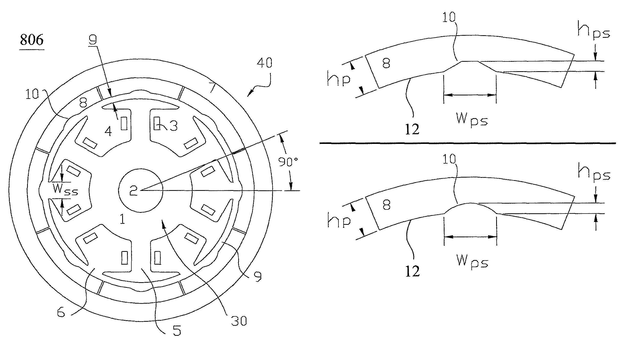
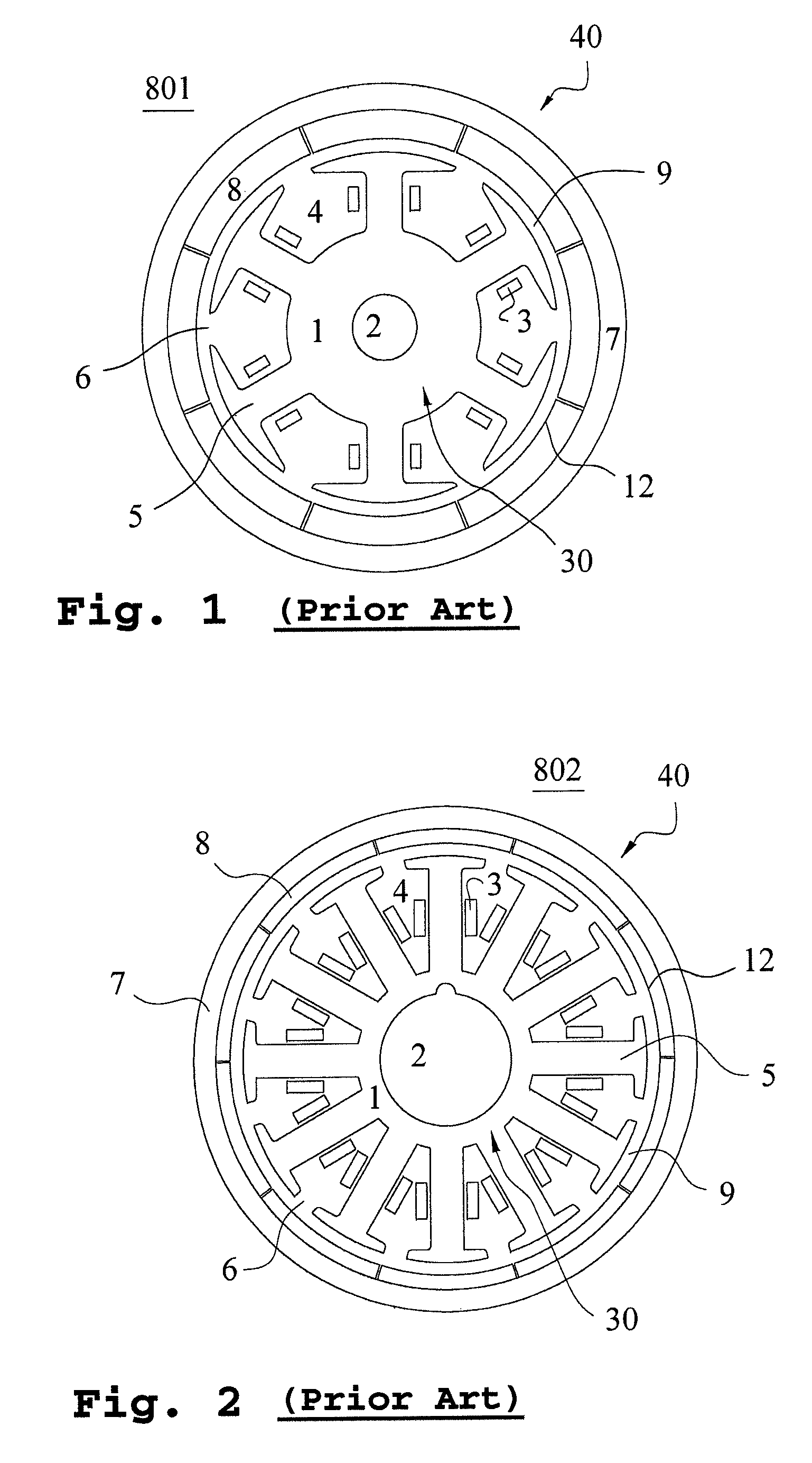
[0073]Subsequently, a preferred embodiment of the present invention is presented as follows to demonstrate the preceding principle. Please refer to FIG. 19, which is a cross-sectional view illustrating the first embodiment regarding the rotary structure of a permanent magnet motor for the present application. The rotary structure 819 of the permanent magnet motor in FIG. 19 is based on the outer rotor permanent magnet motor illustrating in FIG. 1 but the structure for decreasing the cogging torque is further incorporated thereinto. The rotary structure 819 is a permanent magnet motor with eight poles and six slots, but it is not limited to the permanent magnet motor, and the same structure is also applicable to the permanent magnet generator. In FIG. 19, the rotary structure 819 of the permanent magnet motor includes a stator 30 and a rotor 40, in which the cylindrical stator 30 is fixed inside the inner space of permanent magnet motor in order to produce a rotating magnetic field. ...
fourth embodiment
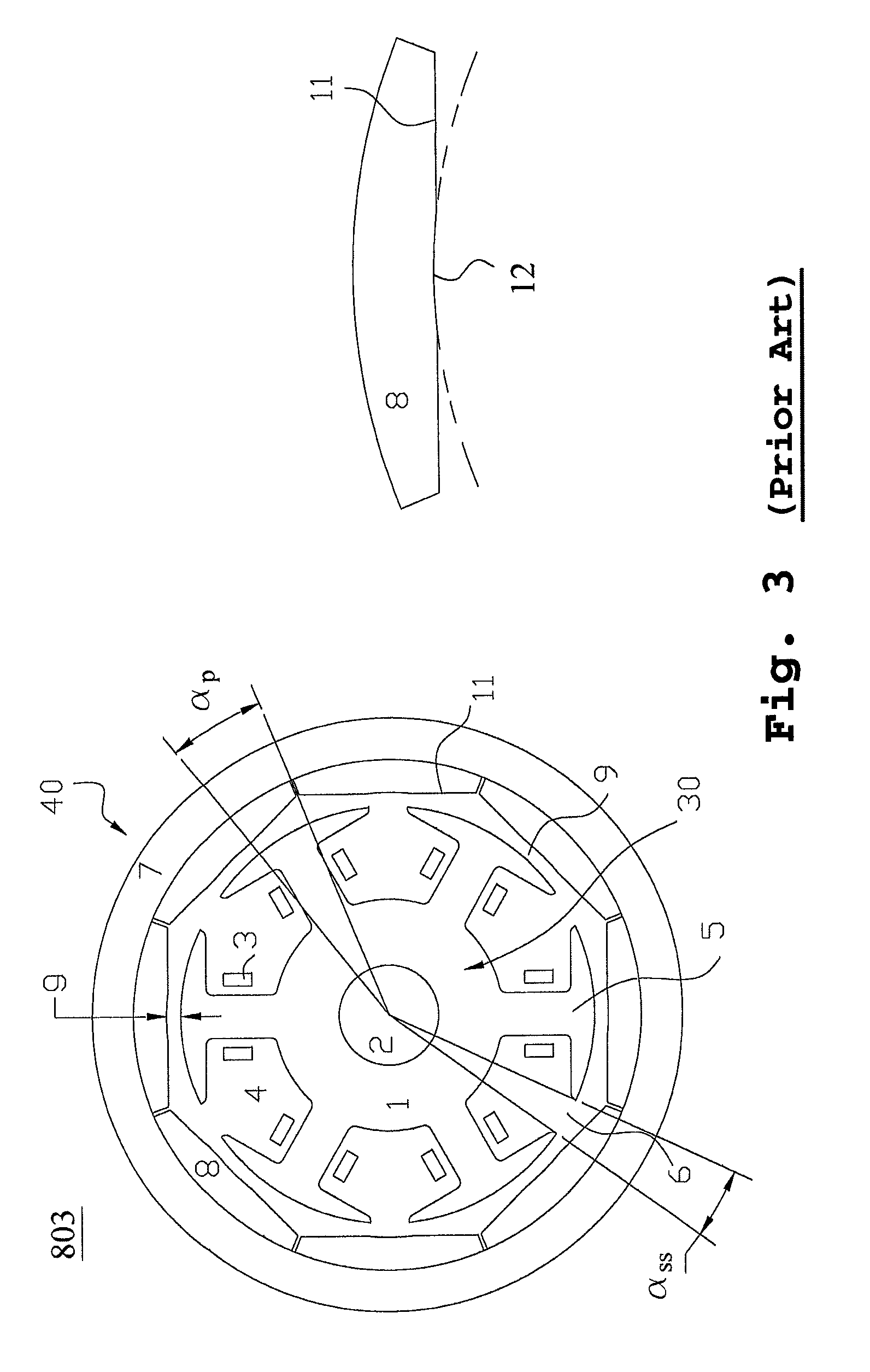
[0093]Subsequently, a preferred embodiment of the present invention is presented as follows to demonstrate the preceding principle. Please refer to FIG. 21, which is a cross-sectional view illustrating the fourth embodiment regarding the rotary structure of a permanent magnet motor for the present application. The rotary structure 821 of the permanent magnet motor in FIG. 21 is based on the outer rotor permanent magnet motor illustrating in FIG. 19, and the relevant computing parameters are defined as follows: P=4, K=6, M=24, f=24 and β0=0°. In accordance with step (q), calculating and choosing an angle, αp, along the circumference direction within an angular range for each angular range corresponding to the pair of the arc-cut surface 11 of the permanent magnets 8. In accordance with step (t): after calculating, the preferred angular positions for disposing the grooves 10 are at the electrical angles of 30°, 90° and 150° along the circumference direction of each permanent magnet 8,...
fifth embodiment
[0095]Please further refer to FIG. 8, in accordance with step (t): after calculating, the preferred angular positions for disposing the grooves 10 are at the electrical angles of 30°, 90° and 150°. After considering the symmetry and the convenience for disposing the grooves, it is chosen to dispose one groove 10 at the arc surface 12 in every 90° along the circumference direction of each permanent magnet 8. And the angle is formed by two lines connecting the two boundaries of two neighboring permanent magnets and intersecting at the center of the stator 40. Please refer to FIG. 22, which is a cross-sectional view illustrating the fifth embodiment regarding the rotary structure of a permanent magnet motor for the present application. The rotary structure 822 of the permanent magnet motor in FIG. 22 is based on the outer rotor permanent magnet motor illustrating in FIG. 19, and the relevant computing parameters are defined as follows: P=4, K=6, M=24, f=24 and β0=180°. In accordance wi...
PUM
 Abstract
Description
Claims
Application Information
 - R&D
- Intellectual Property
- Life Sciences
- Materials
- Tech Scout
- Unparalleled Data Quality
- Higher Quality Content
- 60% Fewer Hallucinations
Browse by: Latest US Patents, China's latest patents, Technical Efficacy Thesaurus, Application Domain, Technology Topic, Popular Technical Reports.
© 2025 PatSnap. All rights reserved.Legal|Privacy policy|Modern Slavery Act Transparency Statement|Sitemap|About US| Contact US: help@patsnap.com


