Rotor and motor

a technology of rotor and motor, which is applied in the direction of dynamo-electric machines, magnetic circuit rotating parts, and shape/form/construction of magnetic circuits, etc., can solve the problem that the magnetic flux of the magnet cannot be effectively utilized

Active Publication Date: 2019-07-11
NIDEC CORP
View PDF6 Cites 1 Cited by
  • Summary
  • Abstract
  • Description
  • Claims
  • Application Information

AI Technical Summary

Benefits of technology

[0178]A circumferential length L1 of the piece portion 46c shown in FIG. 31 is shorter than a circumferential length L2 of the magnet 32. According to this configuration, the magnetic characteristics related to a cogging torque can be improved. Therefore, it is possible to reduce the cogging torque. Furthermore, it is possible to suppress the generation of the magnetic flux loop inside the rotor core 40.

Problems solved by technology

In this motor, there is a concern that the magnetic flux of the magnet could not be effectively utilized in a region of a metal member (a laminate steel plate) positioned between the magnets adjacent to each other in the circumferential direction.

Method used


Image

  • Rotor and motor
  • Rotor and motor
  • Rotor and motor

Examples


Embodiment Construction

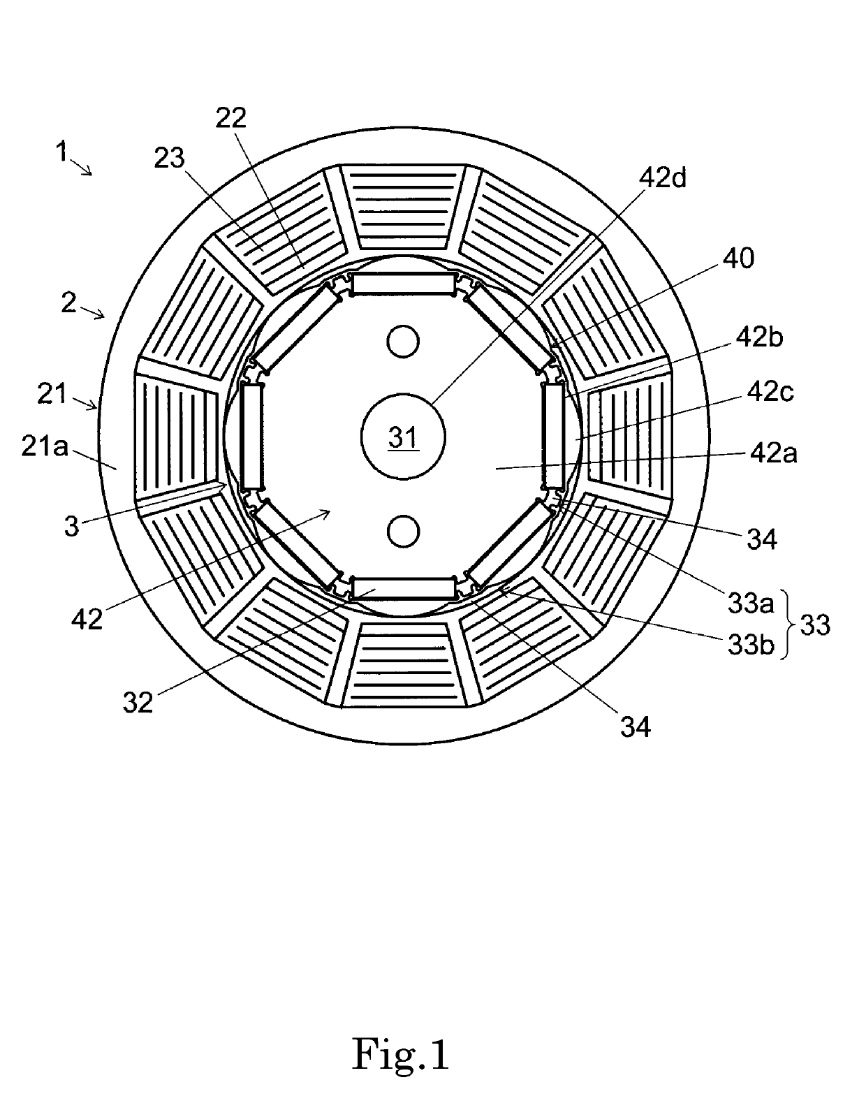
[0037]Hereinafter, example embodiments of the present disclosure will be described in detail with reference to the drawings. In the specification, a direction in which a rotational axis of a motor extends is simply referred to as an “axial direction,” a direction orthogonal to the rotational axis centering around the rotational axis of the motor is simply referred to as a “radial direction,” and a direction along an arc centering around the rotational axis of the motor is simply referred to as a “circumferential direction.” The central axis of the rotor core coincides with the rotational axis of the motor. Also, in the specification, for the sake of convenience of explanation, the axial direction is defined as a vertical direction, and a shape and a positional relationship of each part will be described with a depth direction of the sheet of FIG. 1 serving as the vertical direction of the rotor core, the rotor, and the motor. It should be noted that the definition in the vertical di...


PUM


Abstract

A rotor includes a rotor core in which laminate steel plates extending in a radial direction with respect to a central axis are laminated in an axial direction, and magnets are inserted into the rotor core. Each of the laminate steel plates includes a base portion positioned on a radially outer side of the central axis, and pieces separately disposed on a radially outer side of the base portion with penetrating portions therebetween, and arranged side by side at predetermined intervals in a circumferential direction. The magnets are inserted into the penetrating portions and arranged side by side at predetermined intervals in the circumferential direction. Space portions are provided between the magnets adjacent to each other in the circumferential direction. A circumferential length of the pieces is shorter than a circumferential length of the magnets.

Description

BACKGROUND OF THE INVENTION1. Field of the Invention[0001]The present invention relates to a rotor and a motor.2. Description of the Related Art[0002]Conventionally, a motor in which a rotor having a magnet and a shaft is disposed on a radially inner side of an annular stator having an excitation coil has been widely known. A plurality of magnets are arranged side by side at predetermined intervals in a circumferential direction. In this motor, there is a concern that the magnetic flux of the magnet could not be effectively utilized in a region of a metal member (a laminate steel plate) positioned between the magnets adjacent to each other in the circumferential direction.SUMMARY OF THE INVENTION[0003]According to an example embodiment of the present disclosure, a rotor includes a rotor core in which a plurality of laminate steel plates extending in a radial direction with respect to a central axis are laminated in an axial direction, and a plurality of magnets inserted into the rot...

Claims


Application Information

Patent Timeline
Patent Type & Authority Applications(United States)
IPC IPC(8): H02K1/27H02K1/28H02K21/14H02K15/03
CPCH02K1/276H02K1/28H02K21/14H02K15/03H02K1/22H02K1/27H02K2213/03H02K1/278H02K1/2773H02K1/30
Inventor MIGITA, TAKAYUKIHONDA, TAKESHIMUTO, HIROFUMIFUJIMOTO, OSAMUKITAGAKI, HIROSHINAKAHARA, YASUAKI
Owner NIDEC CORP
Why Eureka
Try Eureka