Magnet-embedded motor with a shew angle forward therein and compressor using same

a magnet-embedded motor and compressor technology, applied in the direction of magnetic circuit rotating parts, piston pumps, magnetic circuit shapes/forms/construction, etc., can solve the problems of incorrect stacked front and back sides, difficult to distinguish whether the steel plate is facing forward or backward, etc., to reduce the cogging torque, low torque ripple, and high efficiency

Active Publication Date: 2021-05-04
SAMSUNG ELECTRONICS CO LTD
View PDF12 Cites 0 Cited by
  • Summary
  • Abstract
  • Description
  • Claims
  • Application Information

AI Technical Summary

Benefits of technology

[0022]It is possible to reduce the cogging torque by stacking the steel plates without reversing the front and back sides to form the stage skew, or by stacking the steel plates capable of easily distinguishing the front and back sides to form the stage skew. Both a sixth-order and twelfth-order of dq coordinates in the harmonic components are reduced, and low torque ripple and high efficiency can be achieved and controllability can be improved.

Problems solved by technology

However, in the structure as illustrated in Patent Document 1, since the bolt holes are formed at regular intervals along the circumferential direction, it is difficult to distinguish whether the steel plate is facing forward or backward.
If the front and back sides are managed in an unaligned state, there may generate a problem that the front and back sides are stacked incorrectly when stacking the steel plates.

Method used


Image

  • Magnet-embedded motor with a shew angle forward therein and compressor using same
  • Magnet-embedded motor with a shew angle forward therein and compressor using same
  • Magnet-embedded motor with a shew angle forward therein and compressor using same

Examples


first embodiment

[0037]First, the internal permanent magnet motor according to the present disclosure will be described.

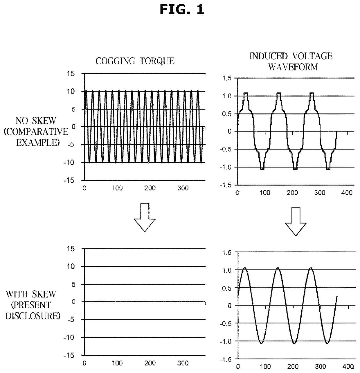
[0038]FIG. 1 is a view illustrating an experimental result of an internal permanent magnet motor according to a first embodiment of the present disclosure.

[0039]The internal permanent magnet motor according to the first embodiment of the present disclosure may be used, for example, in a compressor of a refrigeration cycle, wherein the relationship between a number of poles p and a number of slots s is 1:3, and it has a configuration of distributed winding.

[0040]The rotor constituting such internal permanent magnet motor may be formed in a multi-stage skew, and a predetermined skew angle θs may be formed between the adjacent stages along an axial direction.

[0041]Hereinafter, the rotor having a three-stage skew will be described.

[0042]Generally, in the internal permanent magnet motor having a configuration of the pole number p and the number of slots s, a number of cogging per rotati...

second embodiment

[0059]Next, the internal permanent magnet motor according to the present disclosure will be described.

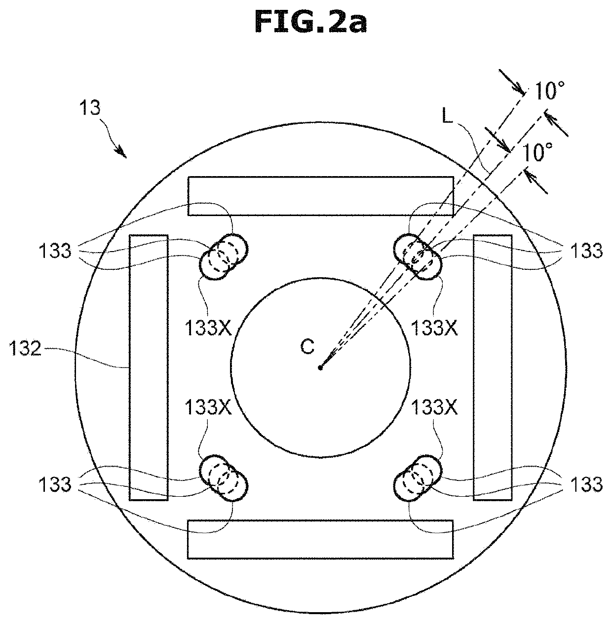
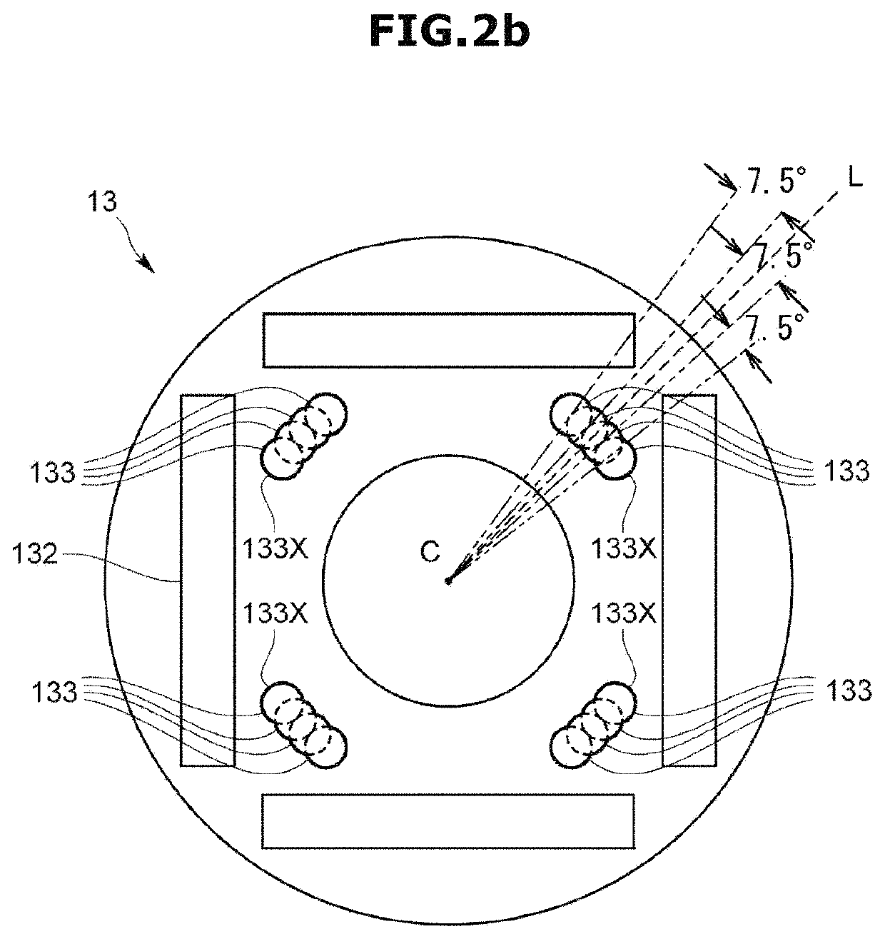
[0060]FIGS. 2A and 2B are schematic views illustrating a steel plate according to a modification of the first embodiment and a second embodiment of the present disclosure.

[0061]The internal permanent magnet motor according to the second embodiment of the present disclosure may have a configuration in which the relationship between a number of poles p and a number of slots s is 1:6.

[0062]Here, skew angles θs1, θs2, θs3 may be obtained from Equations 2 and 4 as in the first embodiment.

[0063]For example, when the number of poles is 4 and the number of slots is 24,

[0064]θs1=5° (corresponding to phase 120°),

[0065]θs2=10° (corresponding to phase 120°), and

[0066]θs3=5° (corresponding to phase 120°)

[0067]As a result, when the skew angle θs is set to 5°, the cogging torque and the twelfth-order harmonic component may be canceled, but the sixth-order harmonic component may not be canceled. Th...

third embodiment

[0086]Next, the internal permanent magnet motor according to the present disclosure will be described.

[0087]The internal permanent magnet motor according to the third embodiment of the present disclosure may be used, for example, in a compressor of a refrigeration cycle, and may be provided with the rotor having the skew formed therein.

[0088]Hereinafter, the rotor, which is a characteristic part of the present disclosure according to the third embodiment, will be described with reference to FIGS. 3 to 5.

[0089]FIG. 3 is a schematic view illustrating a configuration of a rotor according to a third embodiment of the present disclosure, FIG. 4 is a schematic view illustrating a configuration of the rotor according to the third embodiment of the present disclosure, and FIG. 5 is a schematic view illustrating a configuration of the steel plate according to the third embodiment of the present disclosure.

[0090]As illustrated in FIGS. 3 and 4, a rotor 100 according to the third embodiment of...


PUM


Abstract

The present disclosure may reduce cogging torque by stacking steel plates which can form a stage skew by stacking the steel plates without reversing the front and back sides or by forming the stage skew by stacking the steel plates capable of easily distinguishing the front and back sides, and reduce both the sixth-order and twelfth-order dq coordinates of harmonic components, thereby achieving low toque ripple, high efficiency, and improved controllability. To this end, the present disclosure is an internal permanent magnet motor having a rotor in which a predetermined skew angle θs is formed between adjacent stages along the axial direction, wherein the rotor is formed by stacking a plurality of the steel plates having the same shape, each of the steel plates has a group of fastening holes made of the same number of the fastening holes as the number of the stages, and each of the fastening holes constituting the fastening group is formed at a position where the skew angle θs changes along a circumferential direction one by one.

Description

CROSS-REFERENCE TO RELATED APPLICATIONS[0001]This application is a 371 of International Application No. PCT / KR2017 / 005157 filed on May 18, 2017, which claims priority to Japanese Patent Application No. 2016-100756 filed on May 19, 2016 and Japanese Patent Application No. 2017-012626 filed on Jan. 27, 2017, the disclosures of which are herein incorporated by reference in their entirety.BACKGROUND1. Field[0002]The present disclosure relates to an internal permanent magnet motor and a compressor using the same.2. Description of Related Art[0003]As a high-efficiency motor, an internal permanent magnet motor using reluctance torque in addition to magnet torque is used.[0004]The internal permanent magnet motor may include a rotor having a skew formed therein.[0005]The rotor has an upper stage element in which a steel plate is stacked and a lower stage element in which a steel plate is stacked as illustrated in Patent Document 1 (Japanese Patent Publication No. 2013-132138). For example, t...

Claims


Application Information

Patent Timeline
Patent Type & Authority Patents(United States)
IPC IPC(8): H02K1/27H02K29/03H02K1/28H02K21/14
CPCH02K1/276H02K29/03H02K1/28H02K21/14H02K2201/06H02K2213/03F04B35/04F04C15/008H02K15/03F04C11/008F04B17/03
Inventor MUKAI, KATSUHISA
Owner SAMSUNG ELECTRONICS CO LTD
Why Eureka
Try Eureka