Rotor for Electric Power Steering Motor, Electric Power Steering Motor with This, and Manufacturing Therefor

a technology of electric power steering and rotor, which is applied in the direction of stator/rotor body manufacturing, magnetic circuit rotating parts, magnetic circuit shape/form/construction, etc., can solve the problem of difficult assembly so as to reduce the cogging torque, and achieve the effect of reducing the cogging torqu

Inactive Publication Date: 2016-05-19
HITACHI AUTOMOTIVE SYST LTD
View PDF1 Cites 1 Cited by
  • Summary
  • Abstract
  • Description
  • Claims
  • Application Information

AI Technical Summary

Benefits of technology

[0010]According to the present invention, it is possible to provide the rotor for the electric power steering motor capable of being assembled so as to reduce the cogging torque, the electric power steering motor with this, and the manufacturing therefor.
[0011]Any problem, configuration, and effect other than the above-described ones are clarified in descriptions of an example below.

Problems solved by technology

In a case where it is the simple shrink fitting of the shaft and the rotor core, assembling so as to reduce the cogging torque is difficult.

Method used


Image

  • Rotor for Electric Power Steering Motor, Electric Power Steering Motor with This, and Manufacturing Therefor
  • Rotor for Electric Power Steering Motor, Electric Power Steering Motor with This, and Manufacturing Therefor
  • Rotor for Electric Power Steering Motor, Electric Power Steering Motor with This, and Manufacturing Therefor

Examples


example 1

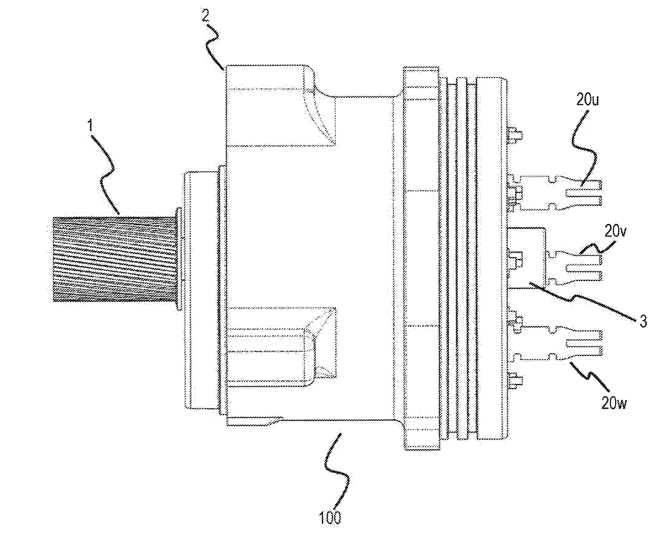
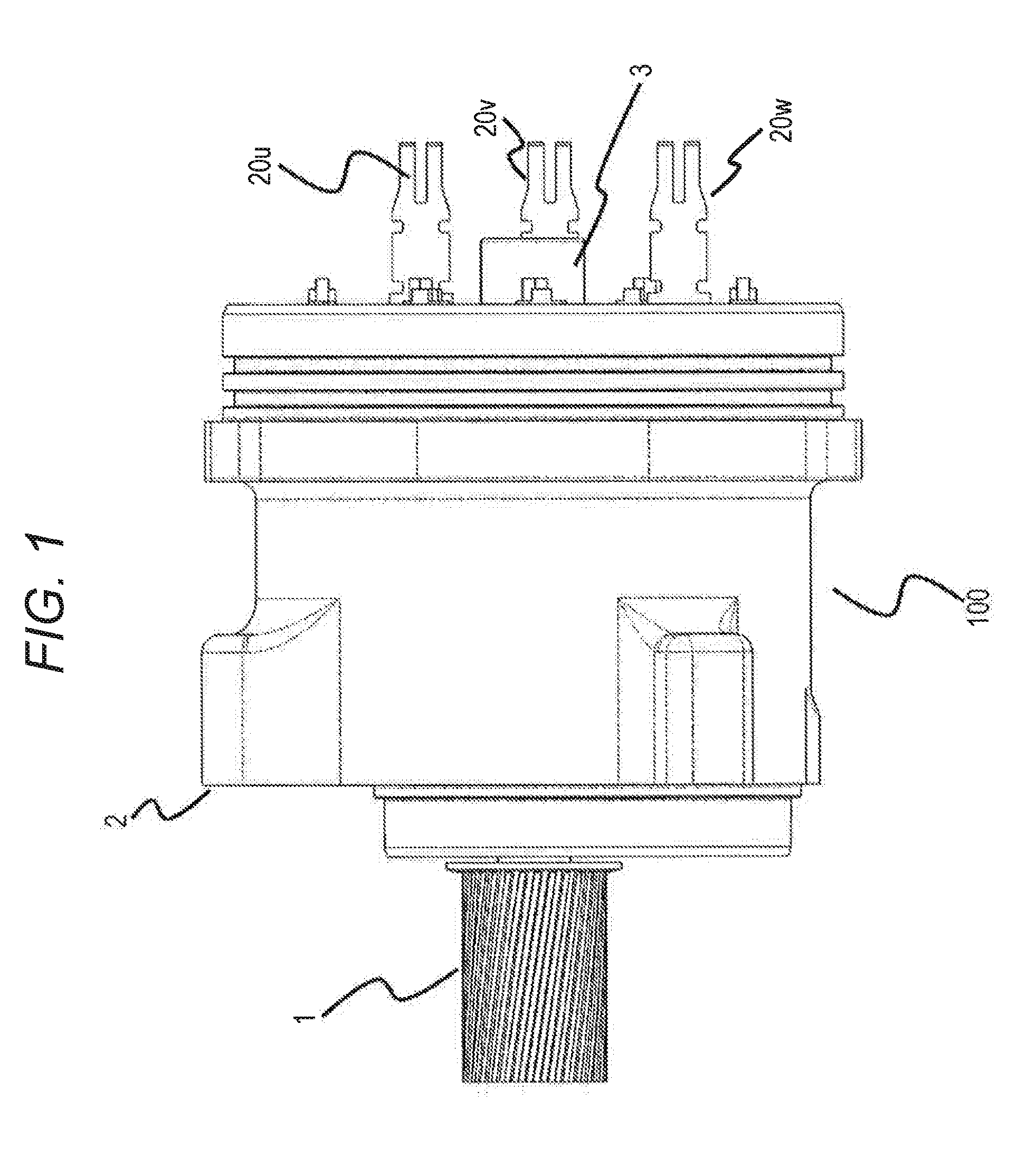
[0021]In FIG. 1, there is illustrated only a motor of an electric power steering (hereinafter, abbreviated as EPS) motor unit (EPS motor 100) constituted of the motor and an ECU, which are mechanically and electrically integrated. In the EPS motor 100, a motor constituent component within a housing 2 is housed. As gear driving for an EPS system, a power transfer mechanism is constituted through a pulley 1 and a belt that are provided to the EPS motor 100. Furthermore, it is structured such that the ECU (not illustrated) is connected on a right side of FIG. 1, and three-phase terminals for U, V, and W phases 20u, 20v, and 20w, which are provided to the motor, are electrically connected to the ECU. The EPS motor 100 is also provided with a magnetic pole sensor 3 for detecting a magnetic pole position of a rotor.

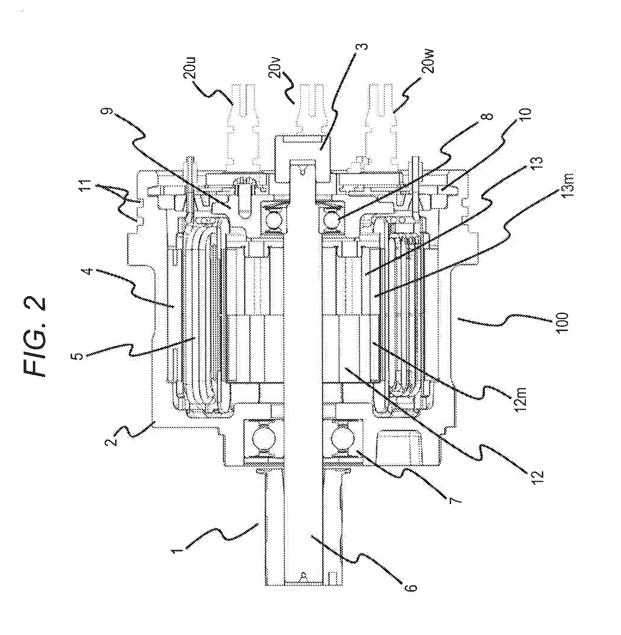
[0022]FIG. 2 is a sectional view of the motor illustrated in FIG. 1. A description is given on a configuration thereof. At a center of the motor, a shaft 6 is arranged, and at ...


PUM


Abstract

A rotor for an electric power steering motor is configured to include a rotor core having a step skew structure constituted of two independent cores as well as to use shrink fitting to fasten the two cores to a shaft. It may also be configured such that a magnetic center of the rotor core is adjusted by controlling a dimension thereof from a tip of the shaft and by shrink fitting the two cores.

Description

BACKGROUND OF THE INVENTION[0001]1. Field of the Invention[0002]The present invention relates to a rotor for an electric power steering motor, an electric power steering motor with this, and manufacturing therefor.[0003]2. Description of the Related Art[0004]JP-2004-153913-A and JP-8-322172-A disclose related arts in this technical field. These official journals disclose a rotor for a motor provided with a rotor core having step skew. On an outer periphery of the rotor core, a magnet is bonded, and the rotor core and a shaft are fixed by shrink fitting. Furthermore, JP-2005-304178-A discloses a rotor having no step skew.SUMMARY OF THE INVENTION[0005]In the above-described Patent Literatures, it is described that in assembly of the rotor, a means of shrink fitting is used to fasten and fix the rotor core and a shaft; however, actually, there is no description on cogging torque, which is a characteristics of the motor. In a case where it is the simple shrink fitting of the shaft and t...

Claims


Application Information

Patent Timeline
Patent Type & Authority Applications(United States)
IPC IPC(8): H02K1/28H02K1/27H02K15/02
CPCH02K1/28H02K1/27H02K15/02H02K15/03H02K1/2781
Inventor KANAZAWA, HIROSHIKAWASAKI, SHOZONAKAYAMA, KENJIHAMADA, YASUNAGAKASHIWA, KOICHIHOSOYA, MASAHIRO
Owner HITACHI AUTOMOTIVE SYST LTD
Why Eureka
Try Eureka