Optical pumping device, optical amplifier, fiber laser, and multicore fiber for optical pumping device
a pumping device and optical amplifier technology, applied in the field of optical amplifiers, can solve the problems of over-conventional technologies, deterioration of the coupling efficiency of the pumping light with the clad pumping fiber, and increase the deformation ratio of the cross-sectional shape, so as to reduce the atmospheric pressure of gaps, reduce the loss, and efficiently input
- Summary
- Abstract
- Description
- Claims
- Application Information
AI Technical Summary
Benefits of technology
Problems solved by technology
Method used
Image

Examples
embodiment 1
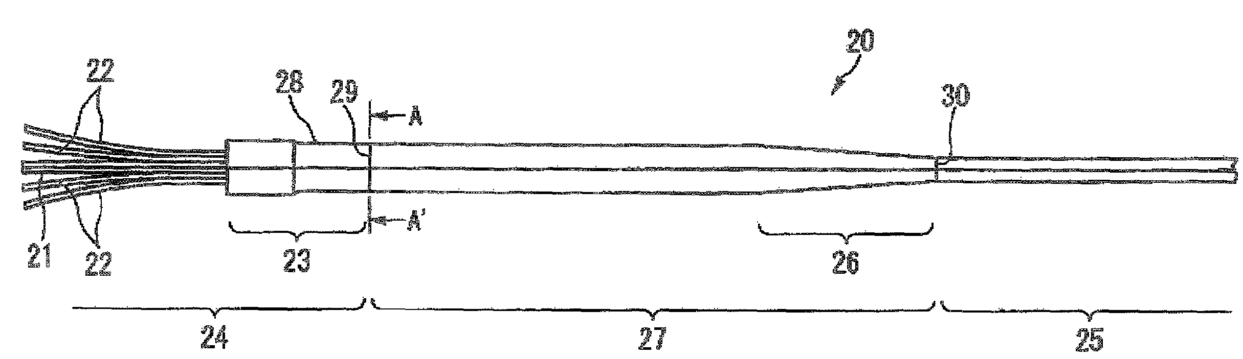
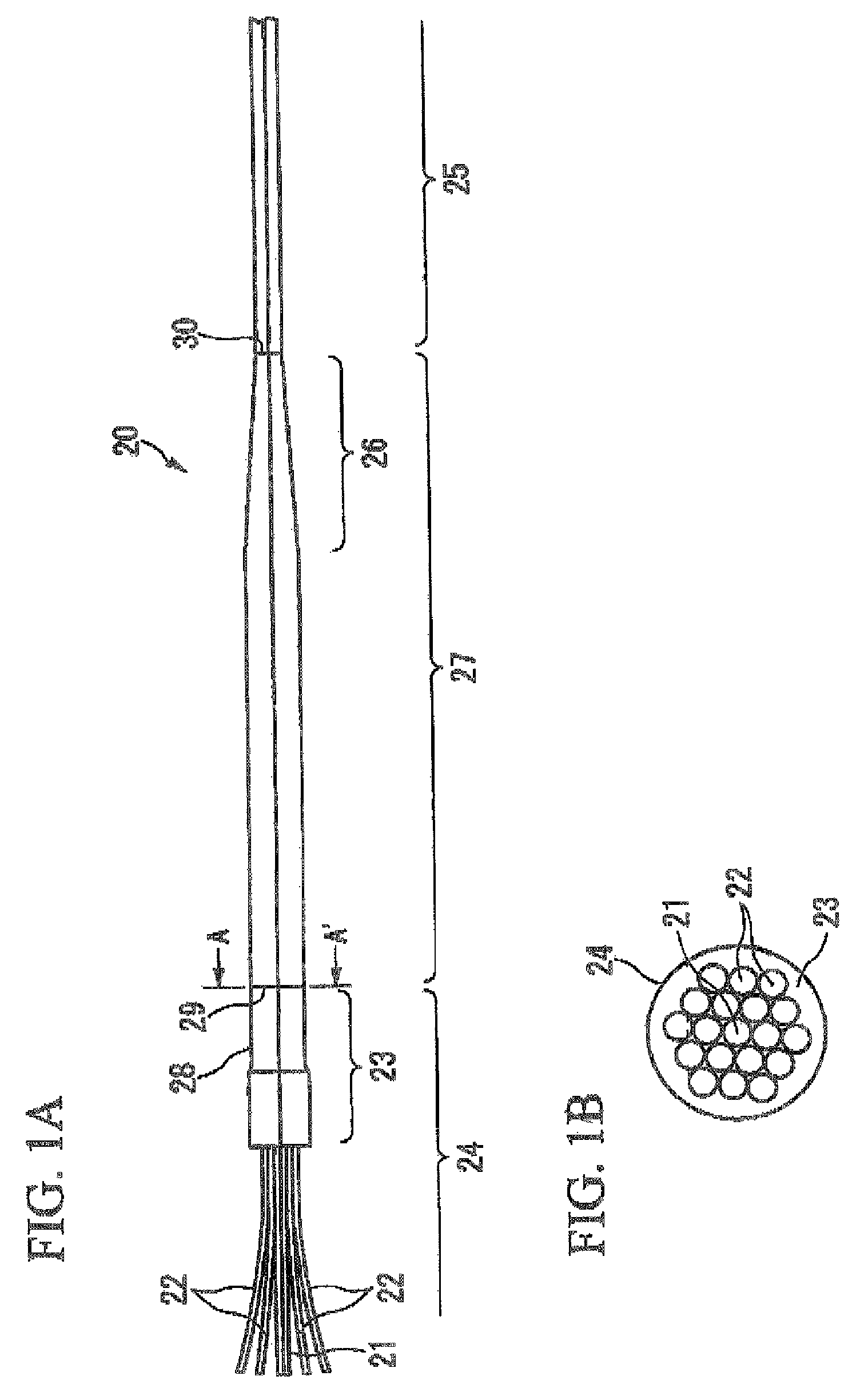
[0078]An optical pumping device having the structure shown in FIG. 1 was manufactured by the following procedure.
[0079]At the center of a multi-hole capillary for inserting 19 cores, a single mode optical fiber having a mode field diameter (hereinafter, referred to as MFD) of about 6 μM (at the wavelength of 1.55 μm), an outer diameter of 125 μm, and a relative refractive index difference Δ of 1% was used as an optical fiber for a signal port, and, at the periphery thereof, 18 MMFs having a core diameter of 110 μm and an outer diameter of 125 μM were used as an optical fiber for a pumping port. The outer diameter of the multi-hole capillary was about 1.2 mm and the diameter of the fine hole was 150 μm.
[0080]The resin-stripped sections of the optical fibers were inserted into the holes of the multi-hole capillary and were pressed into a flat plate, thereby forming an end face of the fiber. After forming the end face via suction by a vacuum pump, in order to decrease the atmospheric p...
embodiment 2
[0086]An optical pumping device having the structure shown in FIG. 4B was manufactured by the following procedure.
[0087]At the center of a multi-hole capillary for inserting 9 fibers, a single mode fiber having an MFD of about 6 μm (at the wavelength of 1.06 μm), an outer diameter of 125 μM, and a relative refractive index difference of 0.45% was used as an optical fiber for a signal port, and, at the periphery thereof, 8 MMFs having a core diameter of 110 μM and an outer diameter of 125 μm were used as a fiber for a pumping port. The outer diameter of the multi-hole capillary was about 440 μm and the diameter of the hole was 135 μm.
[0088]The resin-stripped sections of optical fibers were inserted into the holes of the multi-hole capillary, and the fibers and the capillary were fused and unified by flame, thereby manufacturing a multi-core fiber. Thereafter, the unified section was cut to form an end face of fiber.
[0089]A bridge fiber having an MFD of about 5 μm (at the wavelength o...
embodiment 3
[0094]An optical pumping device having the structure shown in FIG. 8 was manufactured by the following procedure. The structure of FIG. 8 is equal to the structure of FIG. 4B, except that the number of pumping ports 45 of the structure of FIG. 8 is larger by one than that of the structure of FIG. 4B. The number of pumping ports and the flexibility for arrangement of hole position is advantageous to this invention. At the center of the multi-hole capillary having 10 holes, a single mode fiber having an MFD of about 4 μm (at the wavelength of 1.06 μm), an outer diameter of 125 μm, and a relative refractive index difference of 1% was used as an optical fiber for a signal port, and, at the periphery thereof, 9 MMFs having a core diameter of 110 μm and an outer diameter of 125 μm were used as a fiber for a pumping port. The outer diameter of the multi-hole capillary was about 730 μm and the diameter of the hole was 135 μm.
[0095]The resin-stripped sections of the optical fibers were inser...
PUM
 Abstract
Description
Claims
Application Information
 - R&D
- Intellectual Property
- Life Sciences
- Materials
- Tech Scout
- Unparalleled Data Quality
- Higher Quality Content
- 60% Fewer Hallucinations
Browse by: Latest US Patents, China's latest patents, Technical Efficacy Thesaurus, Application Domain, Technology Topic, Popular Technical Reports.
© 2025 PatSnap. All rights reserved.Legal|Privacy policy|Modern Slavery Act Transparency Statement|Sitemap|About US| Contact US: help@patsnap.com