Stacked card edge connector assembly having ejector for removing inserted cards simultaneously

a technology of stacked card and connector assembly, which is applied in the direction of coupling device connection, coupling parts engagement/disengagement, electrical apparatus, etc., can solve the problems of large pulling force and difficulty for operators

Inactive Publication Date: 2010-11-30
HON HAI PRECISION IND CO LTD
View PDF6 Cites 7 Cited by
  • Summary
  • Abstract
  • Description
  • Claims
  • Application Information

AI Technical Summary

Benefits of technology

[0006]Accordingly, an object of the present invention is to provide a card edge connector assembly convenient for an operator to release the cards mounted therein.

Problems solved by technology

There is also another type of a connector assembly for saving the assembling space, in which both cards are inserted into the central slots in a horizontal manner, while if the cards need to be drawn out of the central slot, a large pulling force is needed, which is not easy for the operator.

Method used


Image

  • Stacked card edge connector assembly having ejector for removing inserted cards simultaneously
  • Stacked card edge connector assembly having ejector for removing inserted cards simultaneously
  • Stacked card edge connector assembly having ejector for removing inserted cards simultaneously

Examples


Embodiment Construction

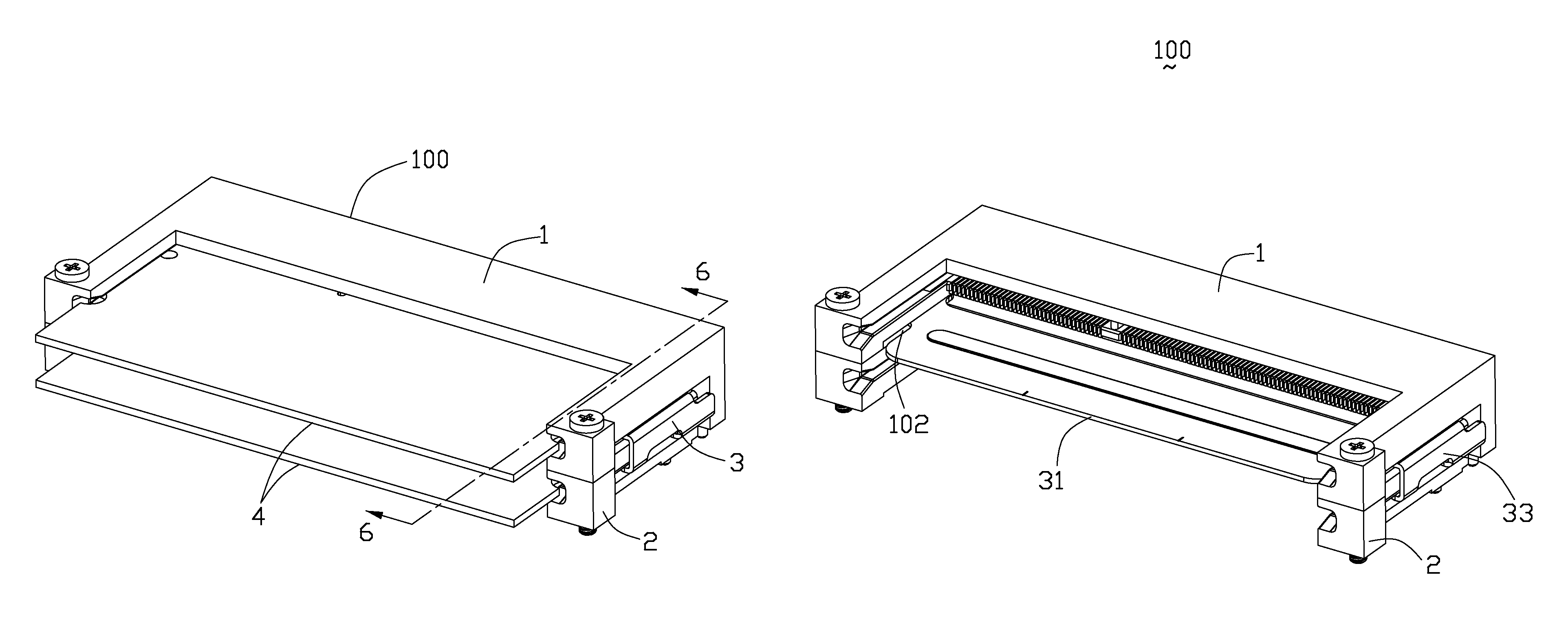
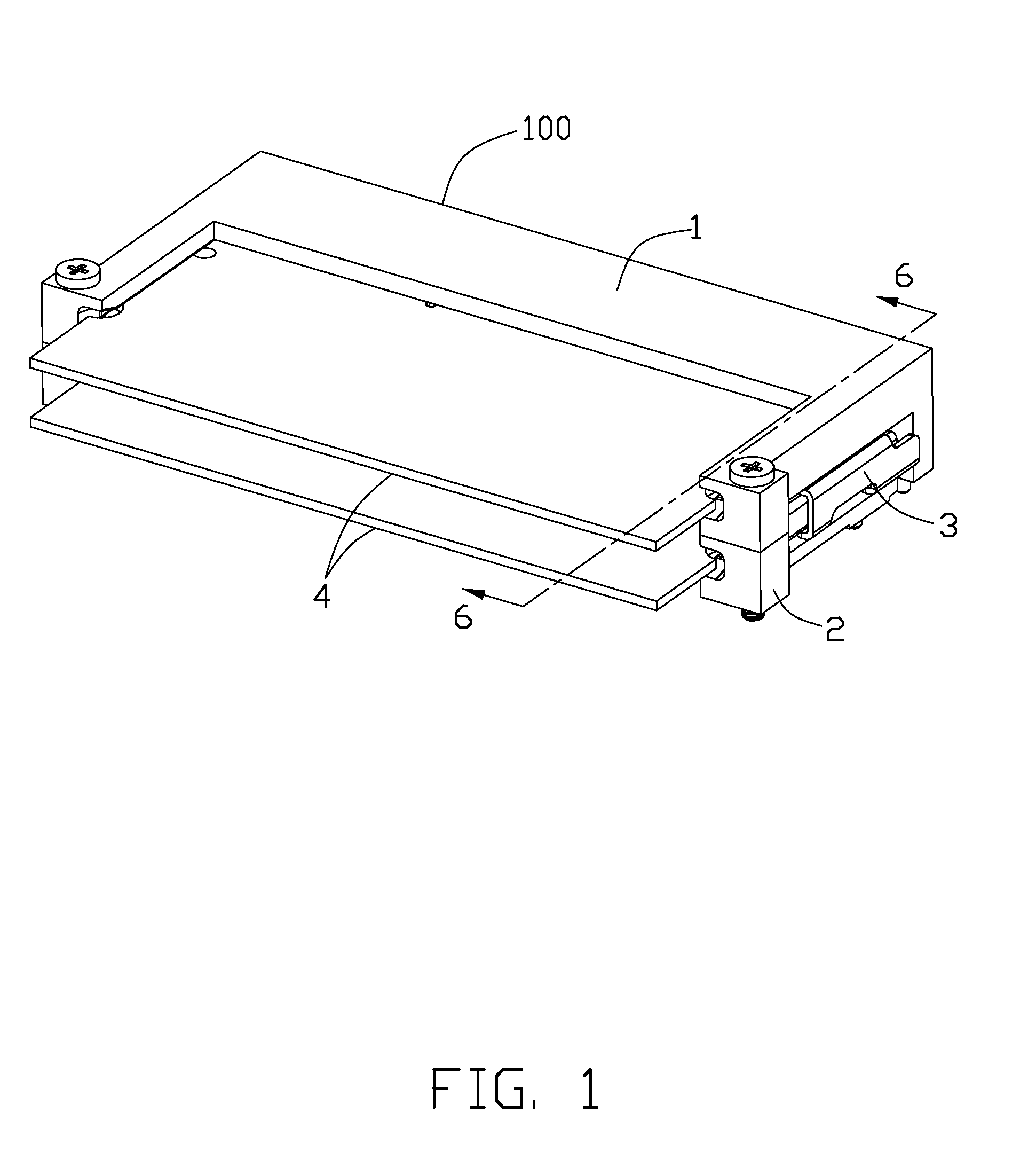
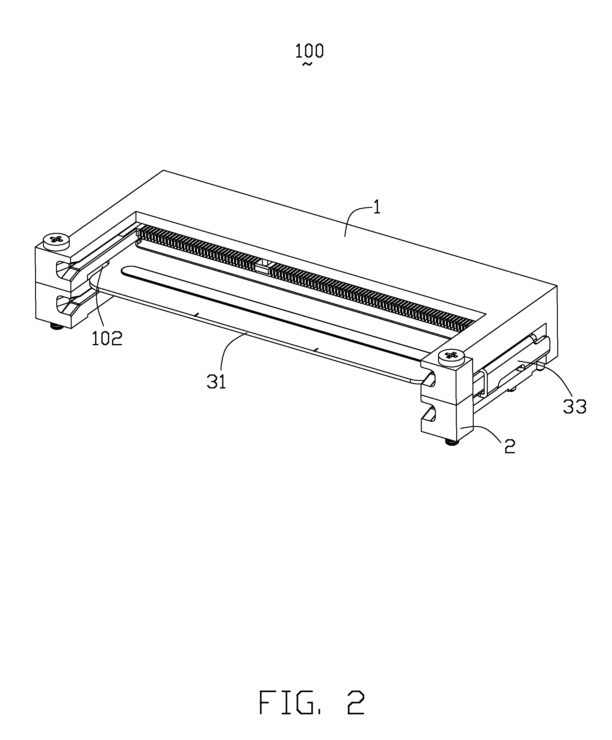
[0021]Reference will now be made to the drawing figures to describe a preferred embodiment of the present invention in detail. Referring to FIGS. 1 and 2, a card edge connector assembly 100 according to the preferred embodiment of the present invention is provided and comprises an upper connector 1 and a lower connector 2 for respectively connecting a pair of cards 4 to a printed circuit board (not shown) and an ejecting device 3 positioned between the upper and lower connectors 1, 2.

[0022]Referring to FIGS. 3 and 4, the upper connector 1 includes an elongated insulative housing 10 defining a central slot 101 expanding along a transverse direction for receiving the card 3 therein and a pair of side arms disposed at opposite ends thereof. A plurality of first terminals 7 are arranged at opposite sides of the central slot 101 for mechanically and electrically contacting with the card 3. Each side arm 11 defines a guiding slot 111 at an inner surface thereof and extending horizontally ...


PUM


Abstract

A card edge connector assembly includes a first connector comprising a first insulative housing defining a first central slot expanding along a transverse direction and a pair of first side arms disposed at opposite ends thereof. A plurality of first terminals are arranged at opposite sides of the first central slot. A second connector stacked with the first connector includes a second insulative housing defining a second central slot expanding along the transverse direction and a pair of second side arms disposed at opposite ends thereof. A plurality of second terminals are arranged at opposite sides of the second central slot. An ejecting device has a first and a second ejecting portions thereon for respectively projecting into the first and second central slots, therefore the ejecting device can release two cards at one time.

Description

BACKGROUND OF THE INVENTION[0001]1. Field of the Invention[0002]The present invention relates to a card edge connector assembly, and more particularly to a stacked card edge connector assembly with a card ejecting device for ejecting both of the inserted cards at one time.[0003]2. Description of the Related Art[0004]U.S. Pat. No. 6,126,472 issued to Choy on Oct. 3, 2000 discloses a connector assembly including a lower housing and an upper housing each generally including the basic structure of the typical SO DIMM connector housing. Each housing defines two rows of passageways on two sides of the central slot in which the corresponding module is received. A plurality of contacts are received within the corresponding passageways wherein the tail of each contact extends downward to engage the corresponding circuit on the PC board on which the connector assembly is mounted. In this type of connector, the cards are slantwisely inserted into the central slots and then rotated to a horizon...

Claims


Application Information

Patent Timeline
Patent Type & Authority Patents(United States)
IPC IPC(8): H01R13/66
CPCH01R12/721H01R12/7047H01R25/006
Inventor ZHU, JIAN-KUANGYANG, XIAO-GAOWANG, ZHEN-HUA
Owner HON HAI PRECISION IND CO LTD
Why Eureka
Try Eureka