Method of filtering low frequency components from power lines

Active Publication Date: 2010-11-30
ROCKWELL COLLINS INC
View PDF17 Cites 1 Cited by
  • Summary
  • Abstract
  • Description
  • Claims
  • Application Information

AI Technical Summary

Benefits of technology

[0007]An advantage of the invention is that sudden or instantaneous changes in power demand can be smoothed out, thereby substantially reducing or eliminating very low frequency electromagnetic emissions.
[0008]The invention provides a power supply for a communications device. The power supply includes a controllable regulator that varies power drawn from a power input according to communications requirements of the communications device. The controllable regulator increases power drawn from the power input immediately before an increase of power is required by the communications device when a magnitude of a rate of change of required power exceeds a predetermined level. An active filter is connected to an output of the controllable regulator. The active filter is controlled to variably divert power that is output from the controllable regulator in excess of what is required by the communications device, wherein electromagnetic emissions resulting from the rate of change of power are reduced.
[0009]The invention also provides a power supply for a radio. The radio employs a waveform characterized by requiring high rates of change of power to fulfill transmission requirements. The radio is further characterized by a predetermined knowledge of when an increase of power will be required to fulfill the transm

Problems solved by technology

Through normal operations, many electronic components generate electromagnetic emissions that may interfere with other electronic components.
This can be problematic when dealing with bursty transmissions and with amplitude modulation (AM) strategies because of the great variation in demand for power. FIG. 1 shows a square radio

Method used


Image

  • Method of filtering low frequency components from power lines
  • Method of filtering low frequency components from power lines
  • Method of filtering low frequency components from power lines

Examples


Example

DETAILED DESCRIPTION OF THE DRAWINGS

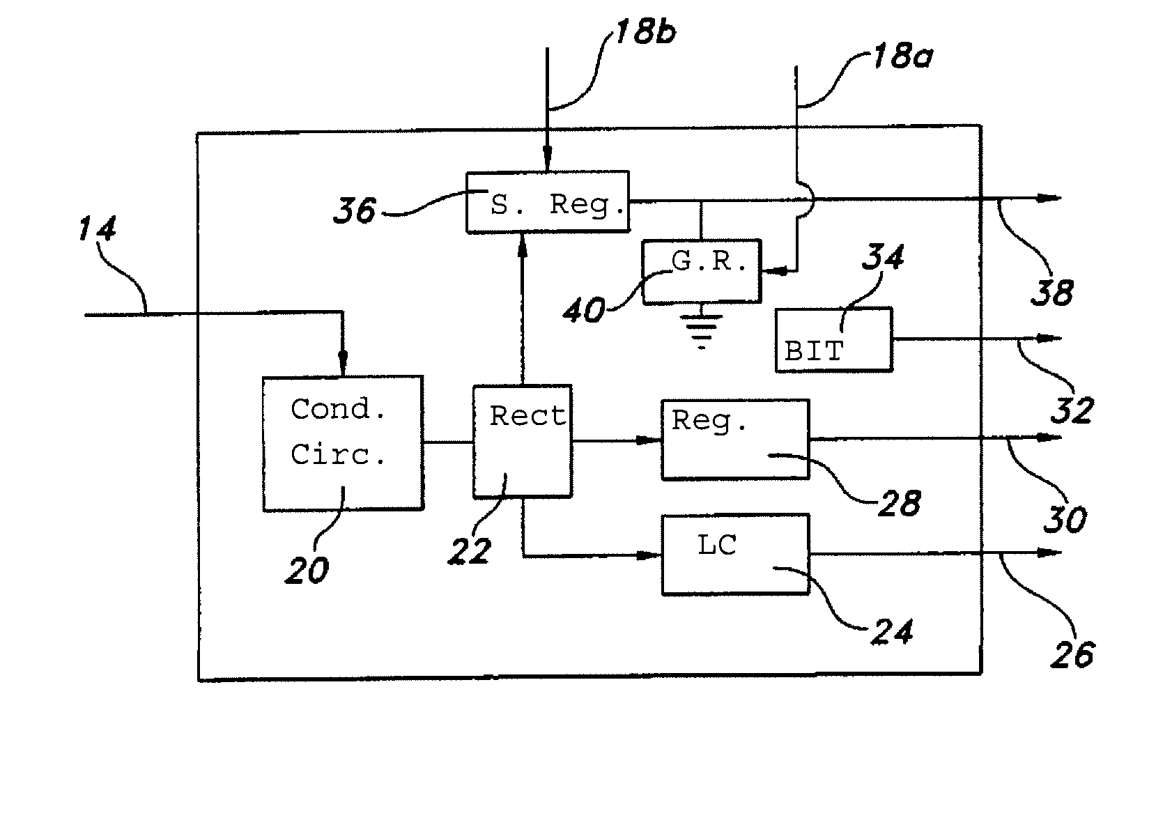
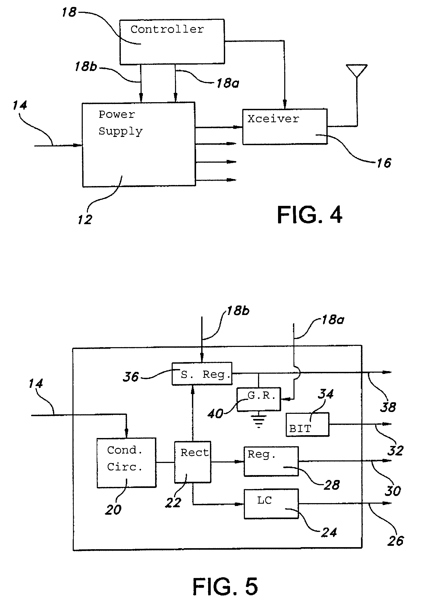
[0026]Describing now the invention with reference to FIGS. 4-5, the invention provides a lightweight method of filtering very low electromagnetic emissions from a power line in a radio system 10. It should be noted that the drawings are not necessarily drawn to scale, and that the dimensions of the various disclosed components have been drawn for the purposes of clarity in understanding the invention. Radio system 10 includes a power supply 12 that accepts, for example, 115 VAC 400 Hz 3-phase power at an input 14. Power supply 12 supplies power through a plurality of outputs to multiple components within the radio system, including transceiver circuitry 16. A controller 18 controls the transmission of radio signals by the transceiver circuitry. According to the invention, controller 18 also provides control signals 18a and 18b to power supply 12, as will be explained further. Radio system 10 is presented in a simplified form, it being understood t...


PUM


Abstract

A power supply for a communications device, including a controllable regulator that varies power drawn from a power input according to communications requirements of the communications device. The controllable regulator increases power drawn from the power input immediately before an increase of power is required by the communications device when a magnitude of a rate of change of required power exceeds a predetermined level. An active filter is connected to an output of the controllable regulator. The active filter is controlled to variably divert power that is output from the controllable regulator in excess of what is required by the communications device, wherein electromagnetic emissions resulting from the rate of change of power are reduced.

Description

FIELD OF THE INVENTION[0001]The invention relates to electronic circuitry, and more particularly, to the reduction of low frequency components from such circuitry.BACKGROUND OF THE INVENTION[0002]Through normal operations, many electronic components generate electromagnetic emissions that may interfere with other electronic components. Small, passive components such as capacitors, inductors, and ferrites can be used to filter out high-frequency electromagnetic emissions. However, there are situations in which very low-frequency electromagnetic emissions must be eliminated or minimized. For example, radio circuitry in some aircraft platforms are required to be analyzed for electromagnetic emissions all the way down to the audio range of frequencies. This can be problematic when dealing with bursty transmissions and with amplitude modulation (AM) strategies because of the great variation in demand for power. FIG. 1 shows a square radio signal pulse. The power requirement to transmit s...

Claims


Application Information

Patent Timeline
IPC IPC(8): H04M1/00
CPCH02J7/345H02M1/12H02J3/01Y02E40/40H02M1/44
Inventor SNODGRASS, TIMOTHY E.
Owner ROCKWELL COLLINS INC
Why Eureka
Try Eureka