Circuit device for reducing common-mode interference of a power converter

Active Publication Date: 2022-02-17
ROBERT BOSCH GMBH
View PDF0 Cites 0 Cited by
  • Summary
  • Abstract
  • Description
  • Claims
  • Application Information

AI Technical Summary

Benefits of technology

The patent text describes a method of reducing interference in electrical systems by using high-impedance components to decouple interference sources from other components. This can improve the performance of filters and prevent common-mode interference. The text also suggests using low-impedance paths for specific purposes.

Problems solved by technology

This results in an inductive coupling to lines which are also routed through this common-mode choke.

Method used


Image

  • Circuit device for reducing common-mode interference of a power converter
  • Circuit device for reducing common-mode interference of a power converter
  • Circuit device for reducing common-mode interference of a power converter

Examples


Embodiment Construction

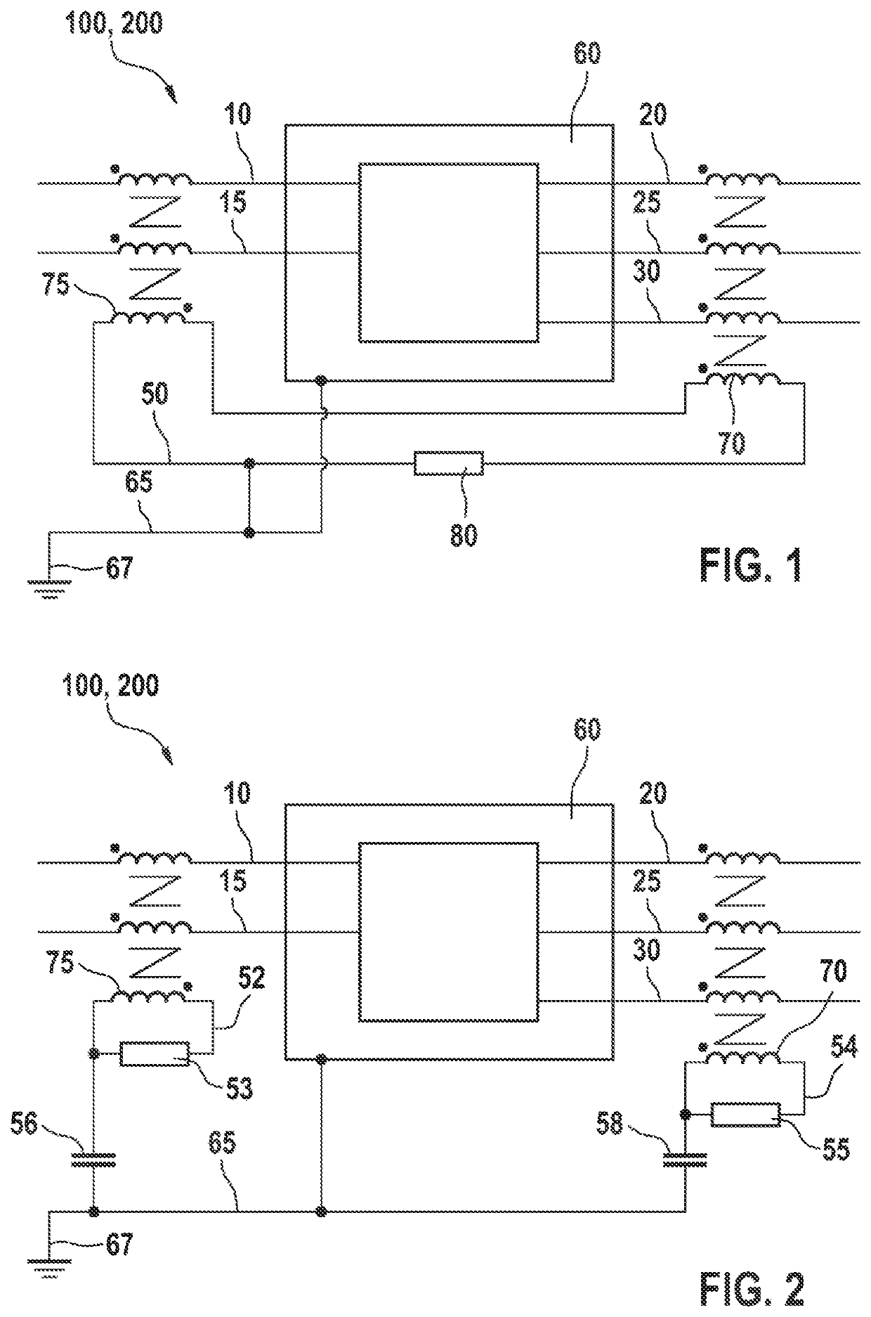
[0037]FIG. 1 shows a first exemplary embodiment in a schematic illustration of a circuit device 100 and a power electronics system 200. The circuit device 100 comprises a short-circuited additional line 50, which can be coupled to an input, preferably by input-side input lines 10, 15, and to an output, preferably by output-side output lines 20, 25, 30, of a power converter 60. The power converter 60, preferably the circuit and / or the housing as a ground connection of the power converter 60, is galvanically connected to a reference conductor 65. To couple the additional line 50 to the input of the power converter 60, the circuit device 100 preferably comprises at least a first common-mode choke 75, through which the input lines 10, 15 and the additional line 50 are routed or wound. For coupling the additional line 50 to the output of the power converter 60, the circuit device 100 furthermore preferably comprises a second common-mode choke 70, through which the output lines 20, 25, 30...


PUM


Abstract

The invention relates to a circuit device (100) for reducing common-mode interference of a power converter (60), the power converter (60) forming a common-mode interference source during operation. The circuit device (100) comprises at least one short-circuited additional line (50), which can be coupled to an input (10, 15) and an output (20, 25, 30) of the power converter (60). The additional line (50) conducts the interference currents produced by the common-mode interference source and returns said interference currents to the common-mode interference source.

Description

BACKGROUND OF THE INVENTION[0001]The invention relates to a circuit device for reducing common-mode interferences of a power converter. The invention furthermore relates to a power electronics system having a corresponding circuit device and an electric vehicle having a power electronics system.[0002]During the operation of voltage transformers, common-mode interferences occur which result in electromagnetic emissions. These should always be minimized during the operation of electrical systems so that these systems do not influence other systems in the surrounding area. Diverse solutions for electromagnetically shielding individual current-carrying lines are known. For example, in this regard, DE102014224267A1 discloses a cable sheath for sheathing an electric line. Alternatively, filter assemblies are known, which consist of capacitors and inductors for minimizing the electromagnetic emission. The known solutions are implemented by means of discrete components which are added to th...

Claims


Application Information

Patent Timeline
IPC IPC(8): H02M1/12H02M7/5387H02M1/44H02P27/06
CPCH02M1/123H02M1/126B60L50/60H02M1/44H02P27/06H02M7/5387H02M1/12H02M7/797B60L50/51B60L2270/147H02M1/0064
Inventor MANUSHYN, ILLIARASEK, GUIDO ALBERT
Owner ROBERT BOSCH GMBH
Why Eureka
Try Eureka