Method and circuit for controlling a pwm power stage

Active Publication Date: 2007-03-29
STMICROELECTRONICS SRL
View PDF4 Cites 11 Cited by
  • Summary
  • Abstract
  • Description
  • Claims
  • Application Information

AI Technical Summary

Benefits of technology

[0034] An object of the invention is to provide a method and a relative control circuit for a power stage with reduced electromagnetic emissions due to the switching of the half-bridge or full-bridge stage.
[0035] The control circuit effectively prevents current peaks that, in prior art power stages, occur at the turn off of the free-wheeling diodes, thus eliminating a significant source of electromagnetic disturbances.

Problems solved by technology

As a result, the power transistors participate together with the diodes in letting the free-wheeling current circulate, thus limiting the current that flows through the diodes when they are turned off.

Method used


Image

  • Method and circuit for controlling a pwm power stage
  • Method and circuit for controlling a pwm power stage
  • Method and circuit for controlling a pwm power stage

Examples


Embodiment Construction

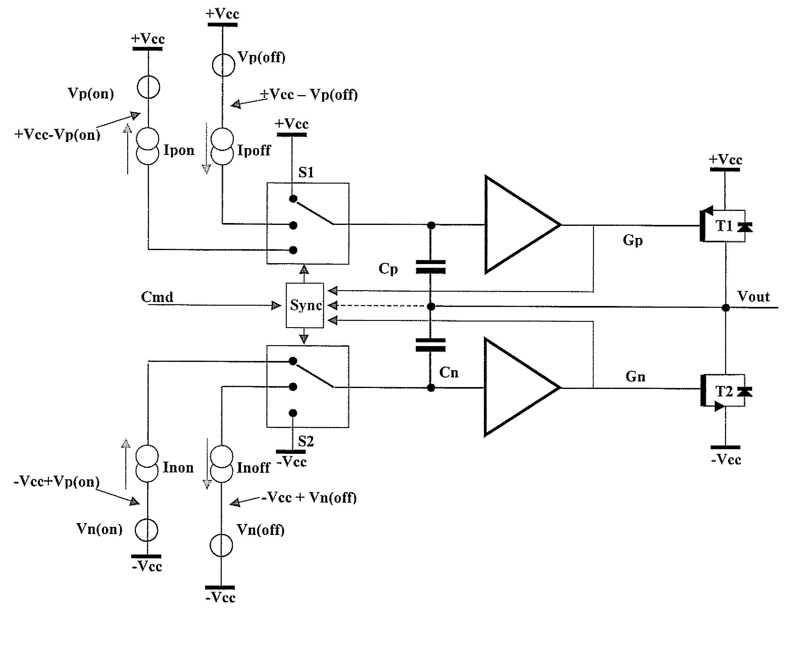
[0051] To better illustrate the invention, reference will be made to the case in which the power stage is in the form of a half-bridge stage, but the same considerations hold also for full-bridge power stages It has been shown that the way the free-wheeling diodes are turned off at the end of the dead times causes the generation of strong cross-conduction current pulses. Investigations carried out for solving the problem led to the conclusion that a way of securely preventing the diodes from being activated during the dead times includes letting the output current Iout flow through an alternative path.

[0052] The MOS transistors are also exploited for letting the free-wheeling current flow while preventing excessively large voltage drops on the free-wheeling diodes. The MOS transistors are, from an electrical point of view, substantially symmetrical structures and thus they are capable of letting the current flow from the drain to the source and vice-versa independently from the fac...


PUM


Abstract

A method for controlling a PWM power stage is based upon dampening current peaks generated by switching of the PWM power stage. The PWM power stage includes at least two MOS transistors of opposite conductivity coupled between an output node of the PWM power stage and respective positive and negative supply lines, and respective free-wheeling diodes. The method includes forming the at least two MOS transistors such that their reverse conduction threshold voltage is smaller than a sum between their forward conduction threshold voltage and a forward voltage on the respective free-wheeling diode at which a pre-established current flows therethrough. The at least two MOS transistors are in a high impedance state by biasing respective control nodes at a turn-off voltage such that their gate-source voltage is between the forward conduction threshold voltage and a null voltage.

Description

[0001] FIELD OF THE INVENTION [0002] The invention relates to power stages, and more particularly, to a method and a relative circuit for controlling a power stage that dampens free-wheeling current peaks when the power stage is switched. BACKGROUND OF THE INVENTION [0003] More and more complex functions are implemented in modern integrated circuit devices that need to be very efficient for keeping as low as possible their operating temperature. Class D audio amplifiers, which are PWM amplifiers, are particularly suitable for satisfying stringent requirements on power dissipation. [0004] The functioning of a class D amplifier is based on the modulation of a high frequency carrier by the signal to be amplified, and on the successive reconstruction of the amplified signal. In particular, in a pulse width modulation (PWM) mode the duty-cycle of a square wave signal, modulated at a constant frequency much greater than the frequency band of the signal to be amplified, is varied depending...

Claims


Application Information

Patent Timeline
IPC IPC(8): H03K7/08
CPCH03F2200/351H03F3/2171
Inventor BOTTI, EDOARDOCAMBIERI, JURI
Owner STMICROELECTRONICS SRL
Why Eureka
Try Eureka