Rail for self-propelled electric trucks

a self-propelled electric trolley and rail technology, applied in the direction of elevated railways, transportation and packaging, ways, etc., can solve the problems of affecting the safety of passengers, and the wheels of the trolley are relatively complicated and vulnerable, so as to facilitate mixed operation, reduce the bending of the sides, and load more heavily

Inactive Publication Date: 2010-12-07
TELEELEVATOR
View PDF20 Cites 13 Cited by
  • Summary
  • Abstract
  • Description
  • Claims
  • Application Information

AI Technical Summary

Benefits of technology

[0007]If each C-shaped side features a central, outwardly displaced running area for the lateral guide rollers of the trolley and upper and lower support surfaces for the side wheel inclined towards the wheel, where the running areas and the support surfaces areas are used in alternation, then the rail can be used by both trolleys with simple wheels without support rims and by trolleys with lateral guide rollers. The simple wheels rest on the lower support surfaces when the trolley is driven on a normal level, or on the upper support surfaces when the trolley is driven suspended overhead. On trolleys with lateral guide rollers, these rollers abut the middle running area of the C-shaped sides of the rails. The novel rail thus facilitates mixed operation by both types of vehicles.
[0008]The special profiling of the C-shaped sides of the rails reduces the bending of the sides when overhead suspension is employed. Less material is required to construct the rail, while at the same time the trolley can be loaded more heavily. The space gained through the upper guide bevel of the side can be used for integrating the assembly grooves.

Problems solved by technology

Because they can be easily damaged, the support rims make the trolley wheels relatively complicated and vulnerable.
The support rims may also cause damage to a surface on which the trolley is placed outside the rail.
Finally, the rail is also relatively complicated, because it requires a ledge on which the support rims can be supported laterally to be present between the sides and the base part of the rail.
They therefore require a relatively high amount of material and are thus costly.
However, this rail may only be used by trolleys with lateral guide rollers.

Method used


Image

  • Rail for self-propelled electric trucks
  • Rail for self-propelled electric trucks
  • Rail for self-propelled electric trucks

Examples


Embodiment Construction

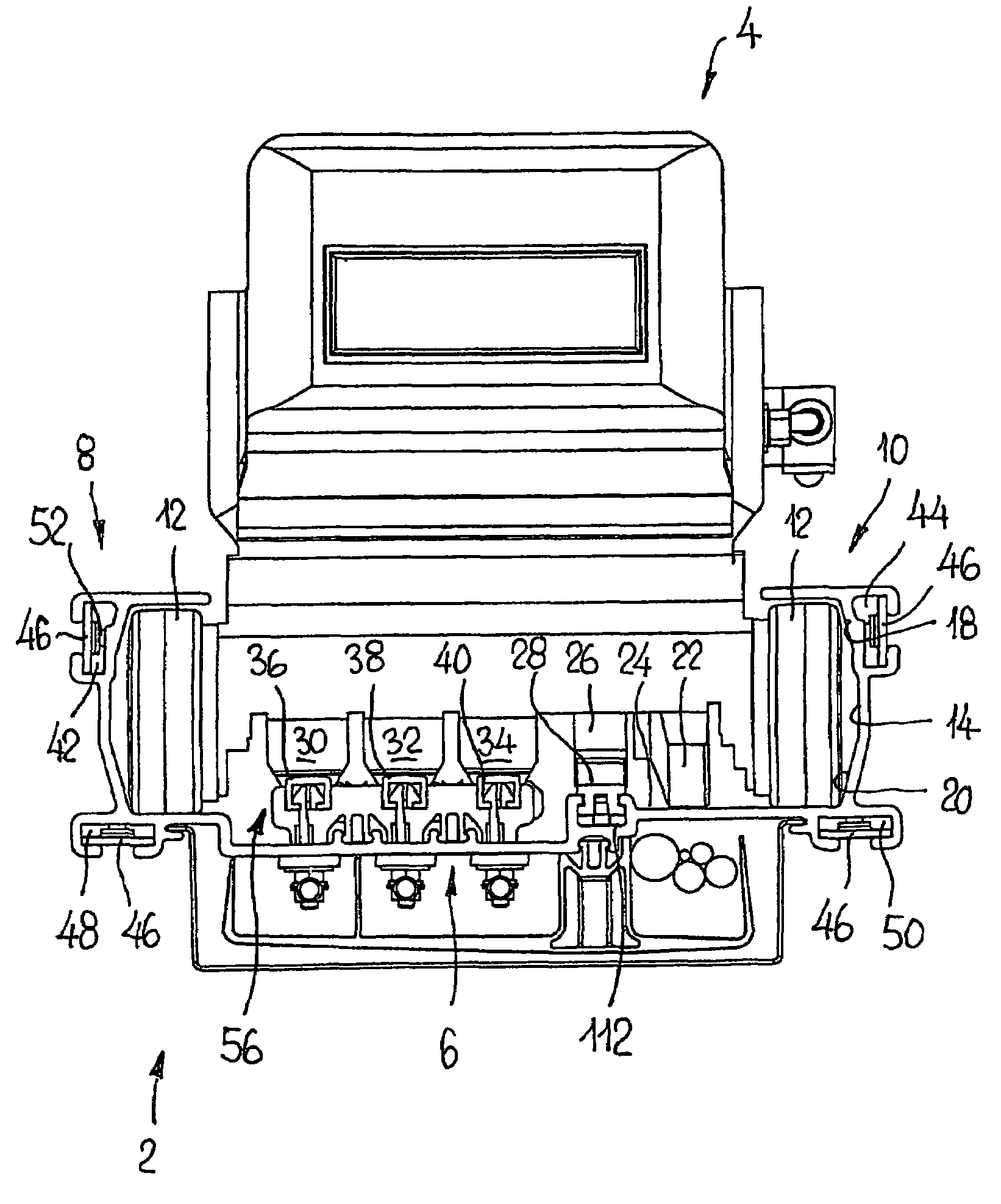
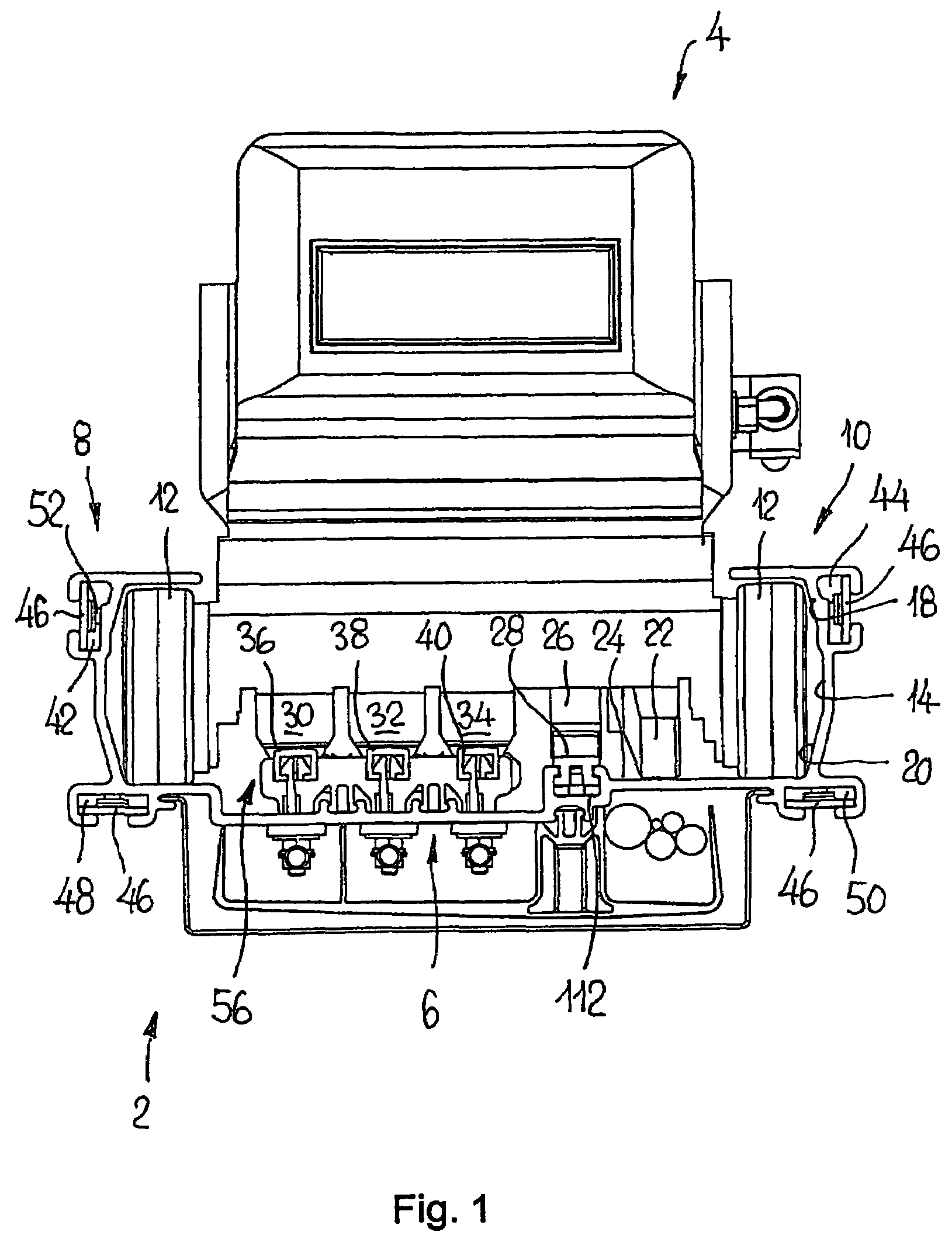
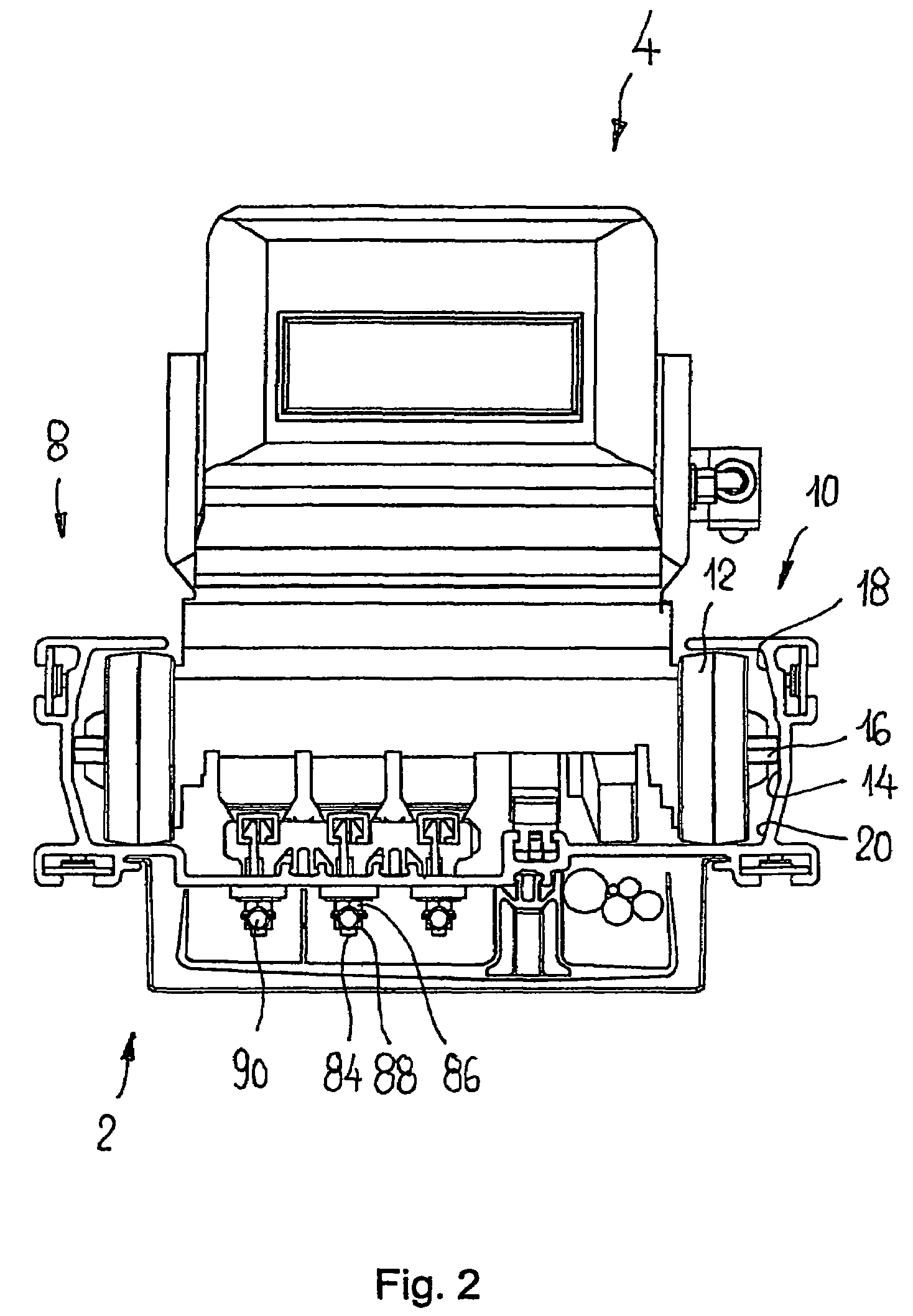
[0024]FIGS. 1 and 2 show a cross section of a segment of a conveyor system that features rails 2 in which a self-propelled trolley 4 is arranged. One such rail 2 features a base part 6 and C-shaped sides 8, 10, which enclose the side wheels 12 of the trolley 4. The C-shaped sides 8, 10 each feature a central, outwardly displaced running area 14 for the lateral guide rollers 16 of the trolley, as well as upper and lower support surfaces 18, 20, each inclined towards the wheel 12. One and the same rail is thus suited for trolleys 4 that feature lateral guide rollers 16, as shown in FIG. 2, and for trolleys 4 without lateral guide rollers, but on which the wheels 12 simply abut the support surfaces 18, 20.

[0025]The wheels 12 and the guide rollers 16 are generally non-powered wheels or rollers without any drive function. Drive is provided on the one hand by a frictional wheel 22 functioning in concert with a corresponding frictional surface 24 of the rail 2, and / or a cog 26 functioning ...


PUM


Abstract

Rail for self-propelled electric trucks, with the rail (2) having a base part (6) and C-shaped side flanks (8, 10) which engage over side wheels (12) of the truck (4). In order to improve the rail, each C-shaped side flank (8, 10) has a central running area (14), which is offset outwards, for side guide rollers (16) of the truck (4) and upper and lower supporting services (18, 20) which run at an angle to the wheel (12) for the side wheels (12), with the running area (14) and the supporting areas (18, 20) being used alternately.

Description

[0001]This application claims priority of PCT application PCT / EP2005 / 012538 having a priority date of Nov. 23, 2005, the disclosure of which is incorporated herein by reference.TECHNICAL FIELD[0002]The invention concerns a rail for a self-propelled electric trolley.BACKGROUND OF THE INVENTION[0003]Rails of the type mentioned above are known from many examples.[0004]CH 515 819 describes such a rail in which the C-shaped sides of the rails engage the side wheels of the trolley. The wheels in turn run on the upper or lower edges of the C-shaped sides. For lateral support, radially projecting support rims, which function in concert with the side parts of the sides of the rail, are provided along the circumferential running surfaces of the trolley wheels on the side facing away from the sides. Because they can be easily damaged, the support rims make the trolley wheels relatively complicated and vulnerable. The support rims may also cause damage to a surface on which the trolley is place...

Claims


Application Information

Patent Timeline
Patent Type & Authority Patents(United States)
IPC IPC(8): B61B5/02E01B25/24
CPCB61B13/04E01B25/22
Inventor HAST, MICHAEL
Owner TELEELEVATOR
Why Eureka
Try Eureka