CMM arm with exoskeleton

A technology of equipment and objects, applied in the field of CMM arms, can solve the problems that manual CMM arms are vulnerable to damage, cannot feed forward downstream process data, and cannot be used.

Active Publication Date: 2010-12-08
ニコンメトロロジーエンフェー
View PDF10 Cites 34 Cited by
  • Summary
  • Abstract
  • Description
  • Claims
  • Application Information

AI Technical Summary

Problems solved by technology

The rigid structure of conventional CMMs and stationary optical probes both have the following disadvantages: they use up cell space on the production line, they are usually only used for measurement and not production operations, they are usually located at the end of the production line, and cannot feed forward data to downstream processes , and the price is expensive, it is difficult to guarantee the return on investment
This limits the applicability of this system and makes it unusable for many applications
Second, ambient lighting conditions must remain close to ideal, otherwise the accuracy of the photogrammetry system will decrease or the system will stop functioning
In practice, this is difficult to establish and often contradicts other lighting requirements for positioning
Third, in such applications, photogrammetric systems often do not have the resolution and speed needed to provide sufficient accuracy for the application
Fourth, such photogrammetric cameras and robots must be rigidly mounted relative to each other
Existing designs of Manual CMM Arms have sophisticated measurement systems that are susceptible to shocks, moments, and violations of operating procedures during use and transport
The existing design of the shipping container is relatively simple and leaves the Manual CMM Arm vulnerable to damage, especially from impact

Method used


Image

  • CMM arm with exoskeleton
  • CMM arm with exoskeleton
  • CMM arm with exoskeleton

Examples


no. 1 example

[0196] Portable Robot CMM Arm

[0197] The first embodiment of this internal CMM arm with exoskeleton is a portable robot CMM arm. This portable robotic CMM arm embodiment includes an internal CMM arm guided by an exoskeleton. The exoskeleton supports and manipulates the internal CMM arm through a transmission device so that it can be accurately measured. The present invention can be implemented according to many layout drawings of the articulated arm of the robot CMM arm. The Robot CMM Arm according to the first embodiment of the present invention has two preferred layouts: 6-axis with 6 joints and 7-axis layout with 7 joints.

[0198] Robot CMM arm joint and segment layout diagram

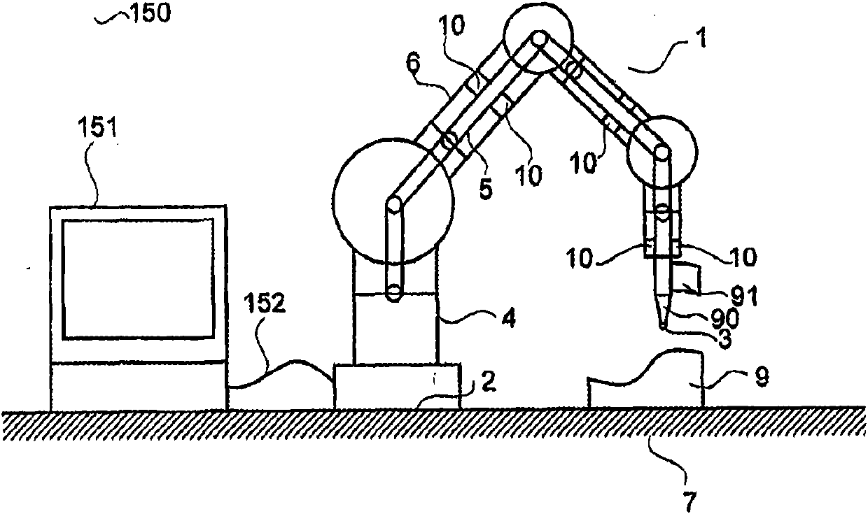
[0199] Figure 1A with 1B To illustrate respectively the preferred 6-axis and 7-axis layout diagrams of the Robot CMM Arm 1 according to the first embodiment of the present invention. The articulated robot CMM arm 1 has a base end 2 and a probe end 3 and includes a set of segments and a rotary join...

no. 2 example

[0645] Industrial Robot CMM Arm

[0646] In this second embodiment, the disclosed industrial robot CMM arm is used to provide accurate robot motion. In this second embodiment, a seven-axis industrial robot CMM arm with a common base section and a common probe section 8 is provided. The common probe section can carry heavy probes or tools and is susceptible to significant forces, while providing accurate position information. Compared with existing industrial robots, the industrial robot CMM arm is not only more reproducible, but also approximately 10 times more accurate. See now Figure 53 , The industrial robot CMM arm 450 has a common base 4, and the common base 4 includes a CMM section 31, a transmission device 171, and a robot exoskeleton section 141. The industrial robot CMM arm 450 also has a common probe section 8 451, which includes a CMM section 838, a transmission device 878, and an exoskeleton section 848. In fact, it provides a rigid transmission 878. The CMM sec...

no. 3 example

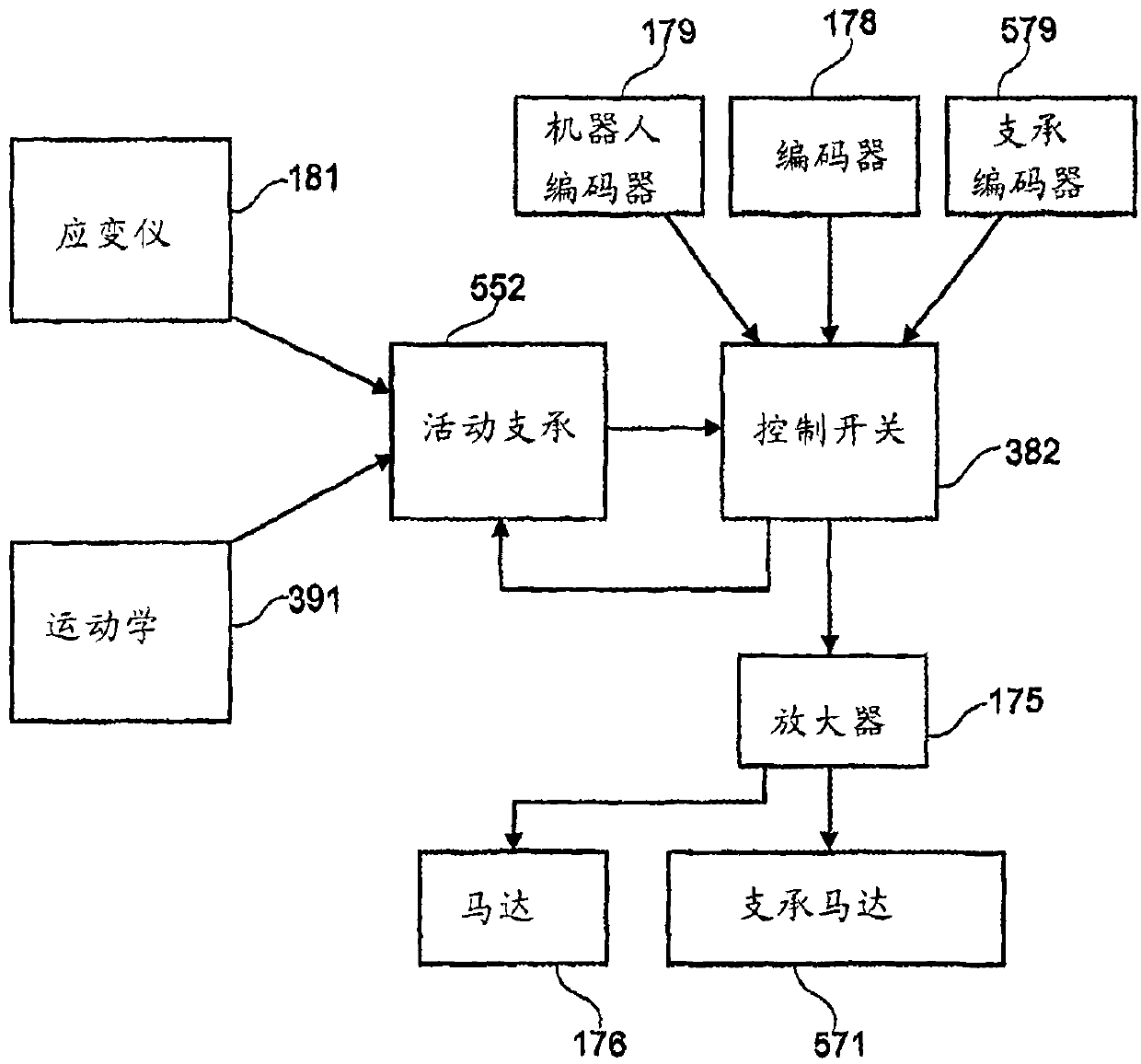
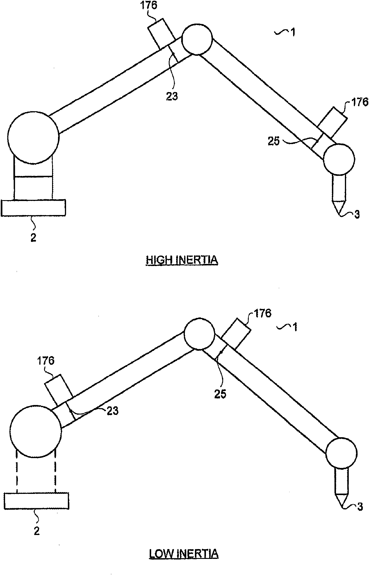
[0713] In this third embodiment, a movably supported robot CMM arm is disclosed. In all the spatial layouts to which it can be moved, it significantly reduces the forces acting on the joints and segments of the internal CMM arm 5. Moment.

[0714] Forces and moments acting on the robot CMM arm of the first embodiment

[0715] In some spatial layouts of the robot CMM arm 1, there is a considerable load acting on the internal CMM arm 5, so that the seven motors that act through the seven exoskeleton joints 1-761-67 of the exoskeleton 6 are provided The setting structure of 176 cannot provide enough control output to reduce these loads. In some spatial layouts, all the weight of the following sections of the internal CMM arm 5 acts on the joint. For example, when the internal CMM arm 5 is located in a vertical space layout, the total weight of the CMM section 2-832-38 directly falls on the CMM joint 151. Similarly, the total weight of the CMM segments 3-8 33-38 directly falls on t...


PUM


Abstract

Apparatus for a CMM Arm with Exoskeleton is provided comprising an Internal CMM Arm with a base end and a probe end, and an Exoskeleton driving the Internal CMM Arm through a plurality of transmission. One or more contact probes, optical probes and tools are mounted on the probe end. The CMM Arm with Exoskeleton is provided in manually operable and automated embodiments. The CMM Arm with Exoskeleton is operable for accurate measurement or for performing accurate operations. Methods are provided for operation of the CMM Arm with Exoskeleton.

Description

Technical field [0001] The invention relates to a device and method for a CMM arm with an exoskeleton for performing precise measurement and manipulation. Background technique [0002] Existing methods of automatic measurement [0003] Automatic measurement of medium to large objects requires a measuring machine accuracy of 0.05mm (+ / -2Sigma), usually 0.025mm (+ / -2Sigma) or higher accuracy. ‘Sigma’ refers to a standard deviation. It is currently carried out in two main ways: (i) a large and expensive conventional computer numerically controlled coordinate measuring machine (CNC CMM) with 3 or more axes; (ii) usually located at the end of the automobile production line The rigid structure of the stationary optical probe in the dedicated unit. For a conventional CMM, the optical probe moves around a stationary object in a highly controlled manner in order to generate accurate data. In the second case, both the optical probe and the object are stationary and positioned according t...

Claims


Application Information

Patent Timeline
Patent Type & Authority Applications(China)
IPC IPC(8): G01B11/00B25J13/08B25J9/02G01B5/008G01B11/03
CPCB25J13/088G01B5/008G01B11/03G05B2219/40305G05B2219/37274
Inventor 斯蒂芬·詹姆斯·克兰普顿
Owner ニコンメトロロジーエンフェー
Why Eureka
Try Eureka