Device for cutting and/or embossing a pre-cut blank or a material web

a technology of pre-cut blanks and devices, which is applied in the field of devices for cutting and/or embossing sheets, pre-cut blanks, or material webs, can solve the problems of non-uniform deformation of roller gaps, deterioration of punching, and non-uniform deformation of between the two rollers, and achieve uniform gap width

Inactive Publication Date: 2008-03-20
WINKLER DUNNEBIER GMBH
View PDF26 Cites 39 Cited by
  • Summary
  • Abstract
  • Description
  • Claims
  • Application Information

AI Technical Summary

Benefits of technology

[0011] It is therefore an object of the present invention to create a device for cutting and / or embossing a sheet, a pre-cut blank, or a material web, which makes it possible to set a uniform gap width of the gap between the cutting and / or embossing roller and the counter-roller, over the extent of their axial width.

Problems solved by technology

Bearer rings have the disadvantage that they heat up due to the Hertz pressure and the slip between the running surfaces that roll on one another, and therefore lead to non-uniform deformations of the roller gap.
Furthermore, dirt that gets onto the bearer rings can cause variations in the gap width, which will lead to deterioration of the punching result.
Therefore, the counter-pressure roller is bent relatively greatly in comparison with the punching roller, so that the gap between the two rollers is deformed in a non-uniform manner, which in turn can have the consequence of a deterioration of the quality of the punching result.
If, in the case of these devices, standard bearings always having more or less play are used to mount the punching roller, the punching roller can be lifted during the punching process, within the framework of the bearing play, and this can lead to a change in the gap width between the two rollers, and therefore to a deterioration of the punching result.
Another disadvantage of the known devices with or without bearer rings s that because of the relatively great distance between the bearing points, relatively great bending of the rollers occurs.
The cutting roller, on the other hand, is additionally bent upward, so that again, a non-uniformly deformed gap occurs.
Because the bearer rings are present, the disadvantages connected with them exist here, as well.

Method used


Image

  • Device for cutting and/or embossing a pre-cut blank or a material web
  • Device for cutting and/or embossing a pre-cut blank or a material web
  • Device for cutting and/or embossing a pre-cut blank or a material web

Examples


Embodiment Construction

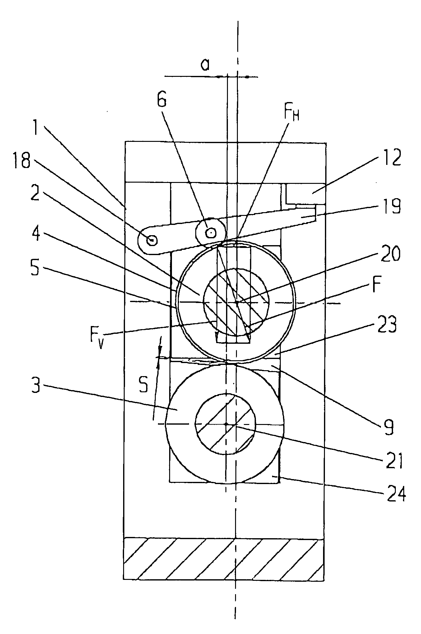
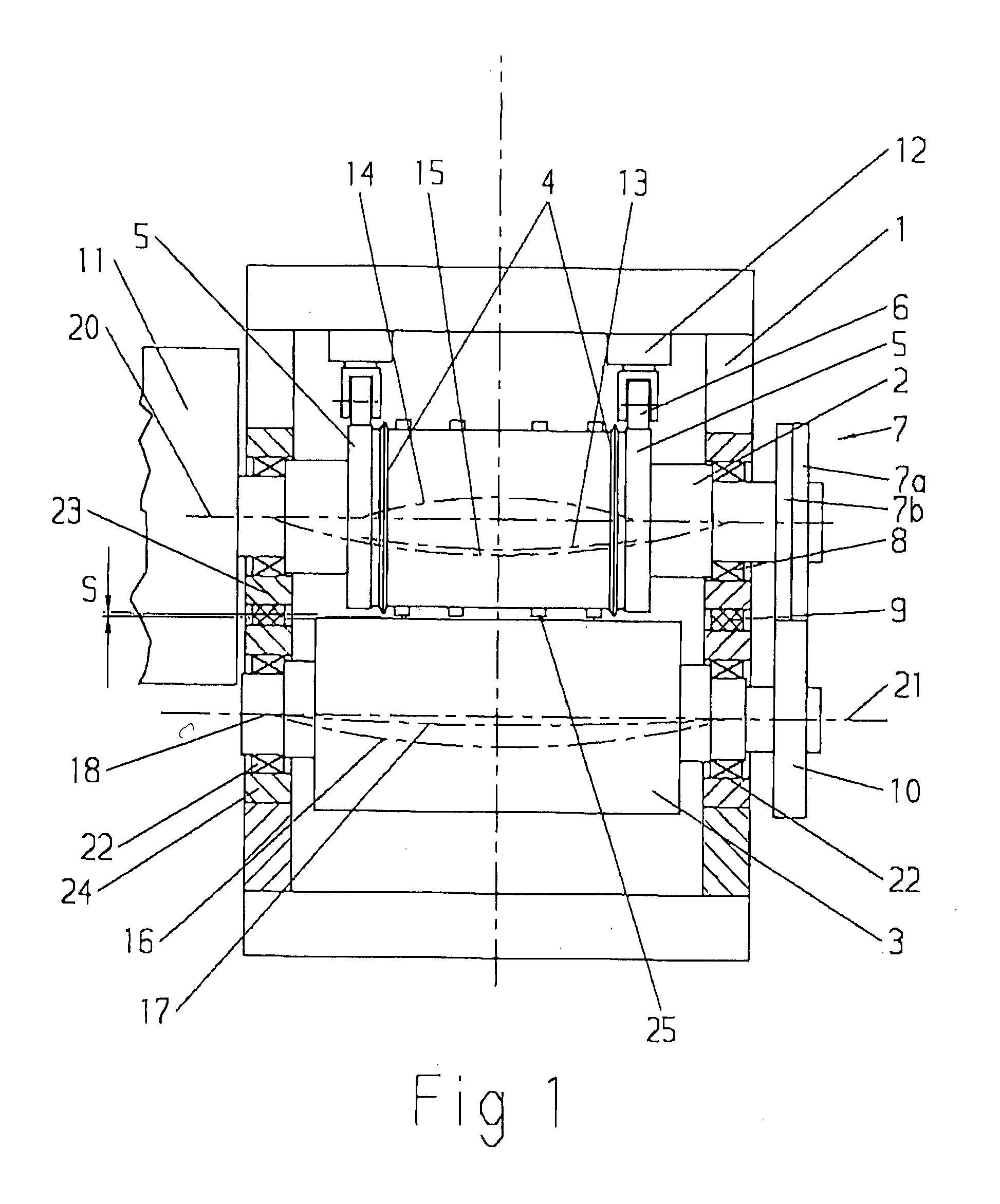
[0027] Referring now in detail to the drawings, FIG. 1 shows a sectional view of an embodiment of the device according to the invention in a radial viewing direction. This is a cutting and embossing roller arrangement for the simultaneous cutting and embossing of paperboard. However, a pure cutting roller arrangement or pure embossing roller arrangement is also possible within the scope of the present invention.

[0028] As shown in FIG. 1, a cutting and embossing roller 2—referred to simply as a cutting roller 2 hereinafter, for the sake of simplicity—is mounted in a frame 1 using two bearings 8, so as to rotate. Bearings 8 are preferably standard bearings. Cutting roller 2 carries two cutting blades 4 as well as embossing pins 25 on its mantle surface, for cutting and embossing paperboard from which pre-cut blanks for folded boxes are produced. The geometry of cutting blades 4 and embossing pins 25, respectively, is structured in accordance with the application case and the cutting ...


PUM


Abstract

A device for cutting and/or embossing a sheet, a pre-cut blank, or a material web has a cutting and/or embossing roller having a longitudinal axis, which is mounted, at its two ends, in at least one bearing so as to rotate, a counter-roller that works together with the embossing roller and is mounted so as to rotate, and a force application device for applying a pressure force to a circumference surface of the cutting and/or embossing roller. This device makes it possible to set a uniform gap width of the gap between the cutting and/or embossing roller and the counter-roller, over its axial width. The pressure force applied to the circumference surface is diverted by the force application device into the at least one bearing by way of at least one part of the cutting and/or embossing roller, so that the pressure force is not applied to the counter-roller.

Description

BACKGROUND OF THE INVENTION [0001] 1. Field of the Invention [0002] The present invention relates to a device for cutting and / or embossing a sheet, a pre-cut blank, or a material web. The sheet can be, for example, a paperboard sheet from which folded box blanks are cut. The pre-cut blank can be, for example, pre-cut blanks for envelopes, which are cut and / or embossed within the framework of the production of finished envelopes. The material web can be, for example, a paper web from which pre-cut blanks for envelopes or labels are cut. [0003] 2. The Prior Art [0004] A punching device for the production of labels is described in German Patent No. DE 103 05 032 B3, which has rotatably mounted punching and counter-pressure rollers. Each of the two rollers has two so-called bearer rings, in the form of closed circumferential running surfaces, on its circumference. The punching roller and the counter-pressure roller are pressed against one another with relatively great forces at these ru...

Claims


Application Information

Patent Timeline
Patent Type & Authority Applications(United States)
IPC IPC(8): B31F1/07
CPCB26D7/2628B26F1/384B26D7/265B31F2201/0753
Inventor RAUEISER, REINHARD
Owner WINKLER DUNNEBIER GMBH
Why Eureka
Try Eureka