Thin film magnetic head, method of manufacturing the same, and magnetic recording apparatus

a technology of magnetic head and film, which is applied in the manufacture of head surfaces, instruments, and heads with metal sheet cores, etc., and can solve problems such as deterioration of recording performance, increased error rate, and increased likelihood of enlarged or distorted recording patterns

Inactive Publication Date: 2005-06-02
TDK CORPARATION +1
View PDF3 Cites 32 Cited by
  • Summary
  • Abstract
  • Description
  • Claims
  • Application Information

AI Technical Summary

Benefits of technology

[0011] The present invention has been achieved in consideration of such problems and its first object is to provide a method of manufacturing a thin film magnetic head, capable of forming a magnetic pole layer as easily as possible.

Problems solved by technology

In the case where the magnetic pole end face of the magnetic pole layer has a rectangular shape, when the thin film magnetic head skews, the recording pattern becomes more likely to be enlarged or to be distorted due to the shape.
If information is recorded on a hard disk in a state where the recording pattern is enlarged or distorted, a crosstalk occurs at the time of reproducing the information, and the error rate increases, that is, the recording performance deteriorates.
However, when mass productivity and manufacture easiness are considered in addition to the performance and manufacture precision as described above to spread thin film magnetic heads, since the lower layer portion corresponding to the inverted trapezoid region and the upper layer portion corresponding to the rectangular region are formed separately in manufacturing a thin film magnetic head, that is, the magnetic pole layer is formed by the process of two steps, the process of forming the magnetic pole layer is complicated and the number of processes required to form the magnetic pole layer is large.

Method used


Image

  • Thin film magnetic head, method of manufacturing the same, and magnetic recording apparatus
  • Thin film magnetic head, method of manufacturing the same, and magnetic recording apparatus
  • Thin film magnetic head, method of manufacturing the same, and magnetic recording apparatus

Examples


Embodiment Construction

[0044] Embodiments of the invention will now be described in detail hereinbelow with reference to the drawings.

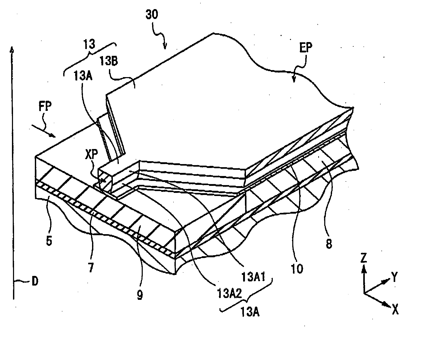
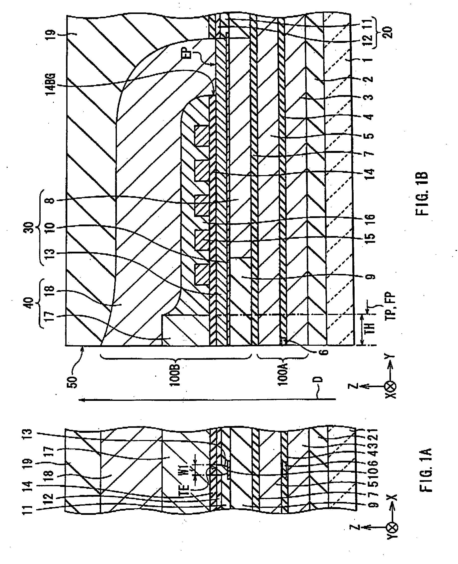
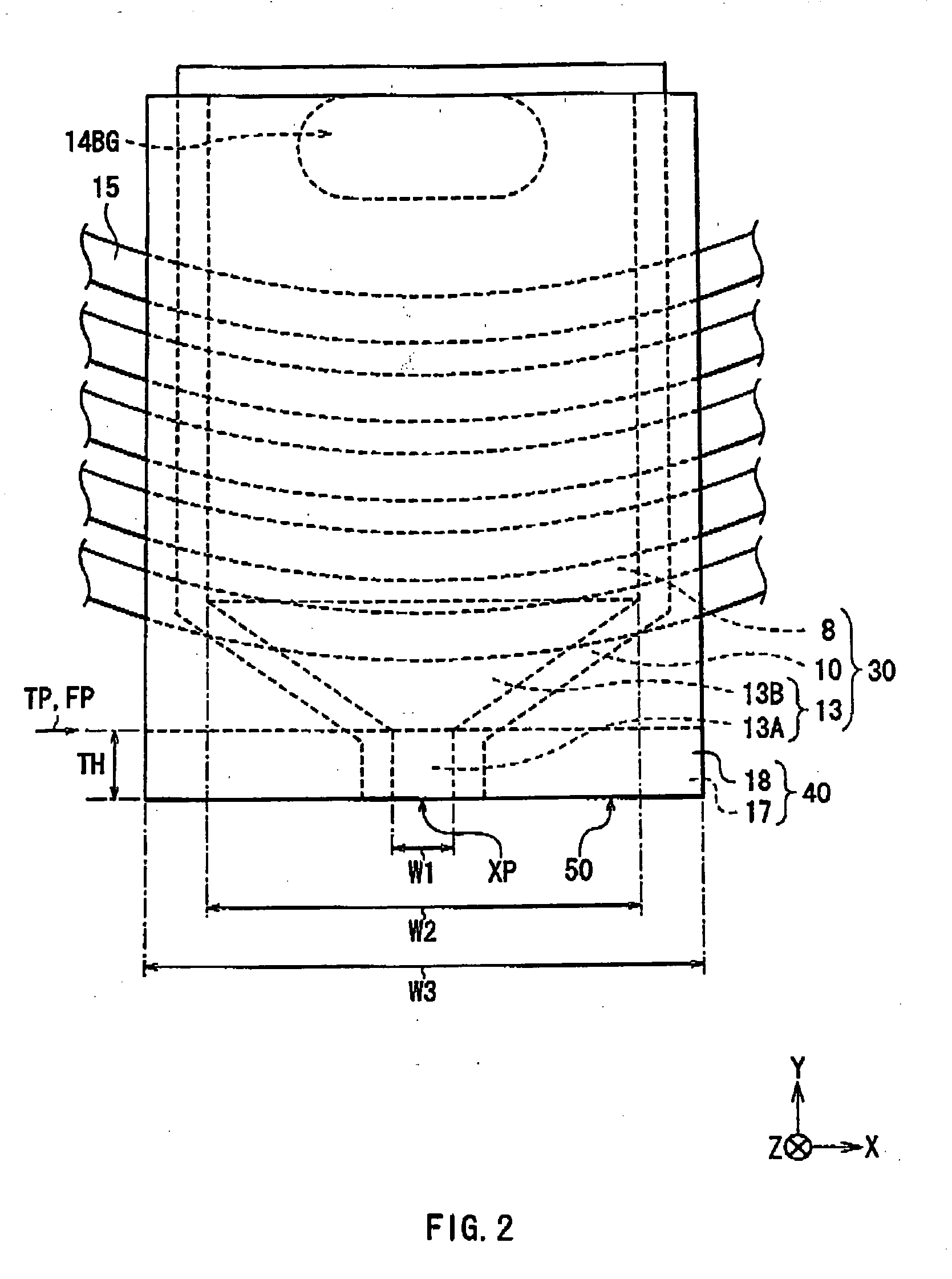
[0045] First, the configuration of a thin film magnetic head according to an embodiment of the invention will be described with reference to FIGS. 1A and 1B to FIG. 4. FIGS. 1A and 1B to FIG. 4 show the configuration of the thin film magnetic head. FIGS. 1A and 1B show a sectional configuration of a thin film magnetic head, FIG. 2 is a plan view of a main portion, FIG. 3 is a perspective view of the main portion, and FIG. 4 is a plan view of a magnetic pole end face. FIG. 1A shows a section parallel to an air bearing surface (section along the XZ plane) and FIG. 1B shows a section perpendicular to the air bearing surface (section along the YZ plane). An upward arrow D shown in FIGS. 1A and 1B and FIG. 3 indicates the travel direction of a magnetic recording medium (not shown) relative to the thin film magnetic head (median travel direction).

[0046] In the following descrip...


PUM

PropertyMeasurementUnit
width W1aaaaaaaaaa
thicknessaaaaaaaaaa
thicknessaaaaaaaaaa

Abstract

The present invention provides a method of manufacturing a thin film magnetic head, capable of forming a magnetic pole layer as easily as possible. By etching a lower insulating layer and the upper insulating layer by RIE using a fluorine-based gas (CF4 or CHF3) or chlorine-based gas (Cl2 or BCl3), a magnetic pole formation space R1 is formed so as to have a uniform width in an upper insulating layer by and a magnetic pole formation space R2 is formed in the lower insulating layer so as to have a width gradually narrowed from width W1 to width W4 with distance from the magnetic pole formation space R1. After that, a plating film is grown in the magnetic pole formation spaces R1 and R2, thereby forming a main magnetic pole layer. Since the main magnetic pole layer is formed in one process by using the structural characteristics of the magnetic pole formation spaces R1 and R2, the process of forming the main magnetic pole layer is simplified and the number of processes required to form the main magnetic pole layer is reduced.

Description

BACKGROUND OF THE INVENTION [0001] 1. Field of the Invention [0002] The present invention relates to a thin film magnetic head having at least an inductive magnetic transducer for recording, a method of manufacturing the same, and a magnetic recording apparatus on which the thin film magnetic head is mounted. [0003] 2. Description of the Related Art [0004] In recent years, in association with improvement in areal density of a magnetic recording medium (for example, a hard disk), improvement in performance of a thin film magnetic head to be mounted on a magnetic recording apparatus (for example, a hard disk drive) is demanded. Known recording methods of a thin film magnetic head are, for example, a longitudinal recording method in which the orientation of a signal magnetic field is set to an in-plane direction (longitudinal direction) of a hard disk and a perpendicular recording method in which the orientation of a signal magnetic field is set to a direction orthogonal to the surface...

Claims


Application Information

Patent Timeline
Patent Type & Authority Applications(United States)
IPC IPC(8): G11B5/127G11B5/31G11B5/147
CPCG11B5/1278G11B5/3116G11B5/3163Y10T29/49032Y10T29/49041Y10T29/4906Y10T29/49043
Inventor MATONO, NAOTOHARADA, TATSUYASHOJI, SHIGERU
Owner TDK CORPARATION
Why Eureka
Try Eureka