Control mechanism for a feed and tension unit in a strapping apparatus

a technology of tension unit and control mechanism, which is applied in the direction of paper/cardboard containers, bundling articles, bundling machine details, etc., can solve the problems of time-consuming process of clearing strap path from complicated series of strap guide, affecting the stability of strapping apparatus, etc., and achieves the effect of easy modification and variable apparatus

Inactive Publication Date: 2002-09-19
SAMUEL MANU TECH
View PDF31 Cites 32 Cited by
  • Summary
  • Abstract
  • Description
  • Claims
  • Application Information

AI Technical Summary

Benefits of technology

0010] The present invention improves upon prior strapping devices, and provides additional benefits, such as by providing variability in the apparatus that can be easily altered to fit various production and package requirements and by employing a control system that monitors operating signals and transmits control signals accordingly.

Problems solved by technology

Although desirable results are achievable using the prior art strapping machines 100, some operational drawbacks exist.
The bends and turns in the strap path may induce kinks in the strap that may subsequently lead to feeding difficulties.
If the strap becomes jammed in the feed and tension unit 116, the process of clearing the strap path from the complicated series of strap guides may be time-consuming and may require machine downtime.
Another disadvantage of the prior art strapping machines is that the drive assemblies of the sealing head 122 and the feed and tension unit 120 are typically complicated designs featuring a one or more gear boxes.
Often these gear boxes are complicated and must transfer the drive forces through a 90 degree angle.
Generally, the cost of fabricating the drive assembly increases with the design complexity, adding to the ultimate cost of the strapping machine.

Method used


Image

  • Control mechanism for a feed and tension unit in a strapping apparatus
  • Control mechanism for a feed and tension unit in a strapping apparatus
  • Control mechanism for a feed and tension unit in a strapping apparatus

Examples


Embodiment Construction

[0045] The present disclosure is directed toward apparatus and methods for strapping bundles of objects. Specific details of certain embodiments of the invention are set forth in the following description, and in FIGS. 2-25, to provide a thorough understanding of such embodiments. A person of ordinary skill in the art, however, will understand that the present invention may have additional embodiments, and that the invention may be practiced without several of the details described in the following description.

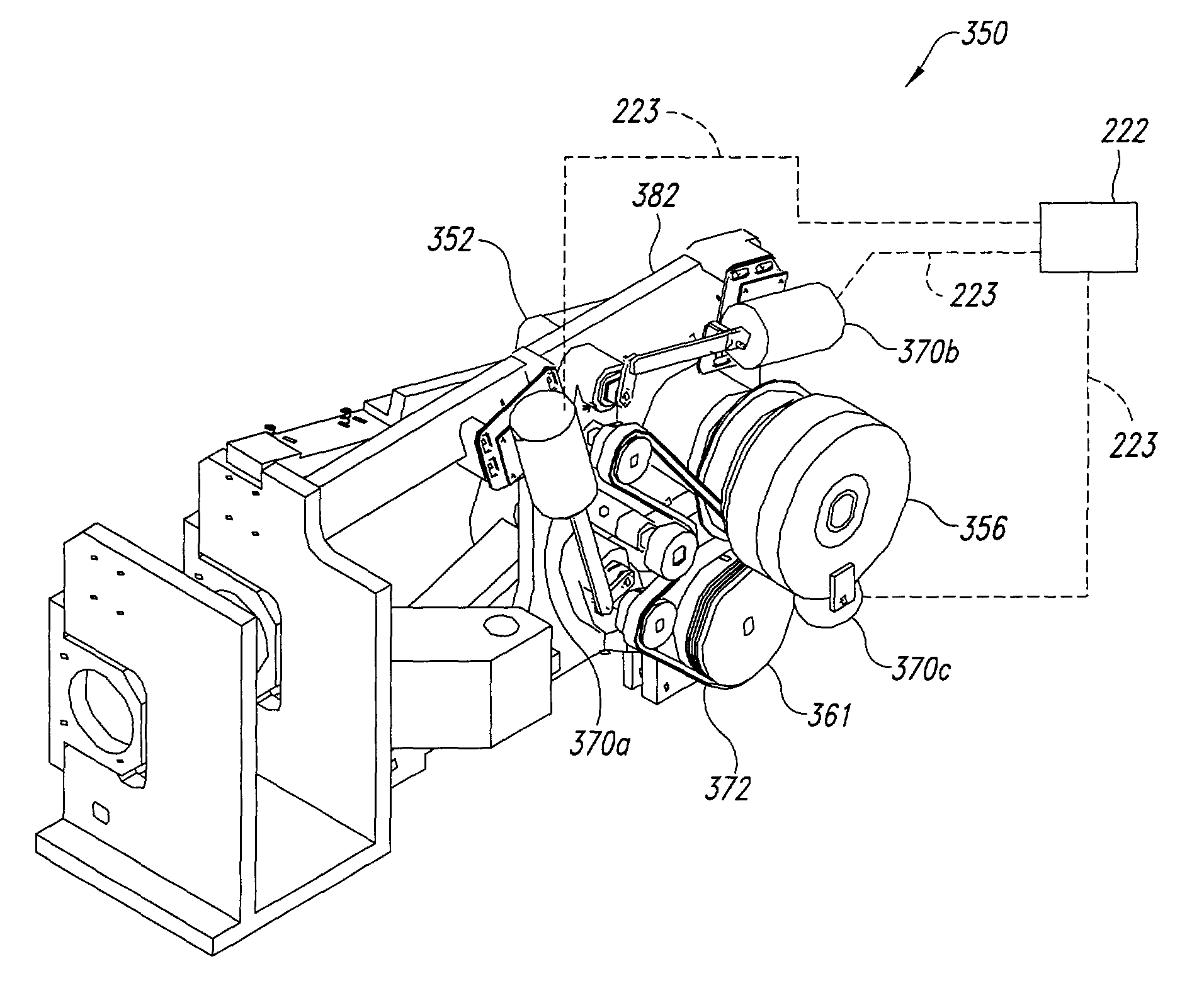
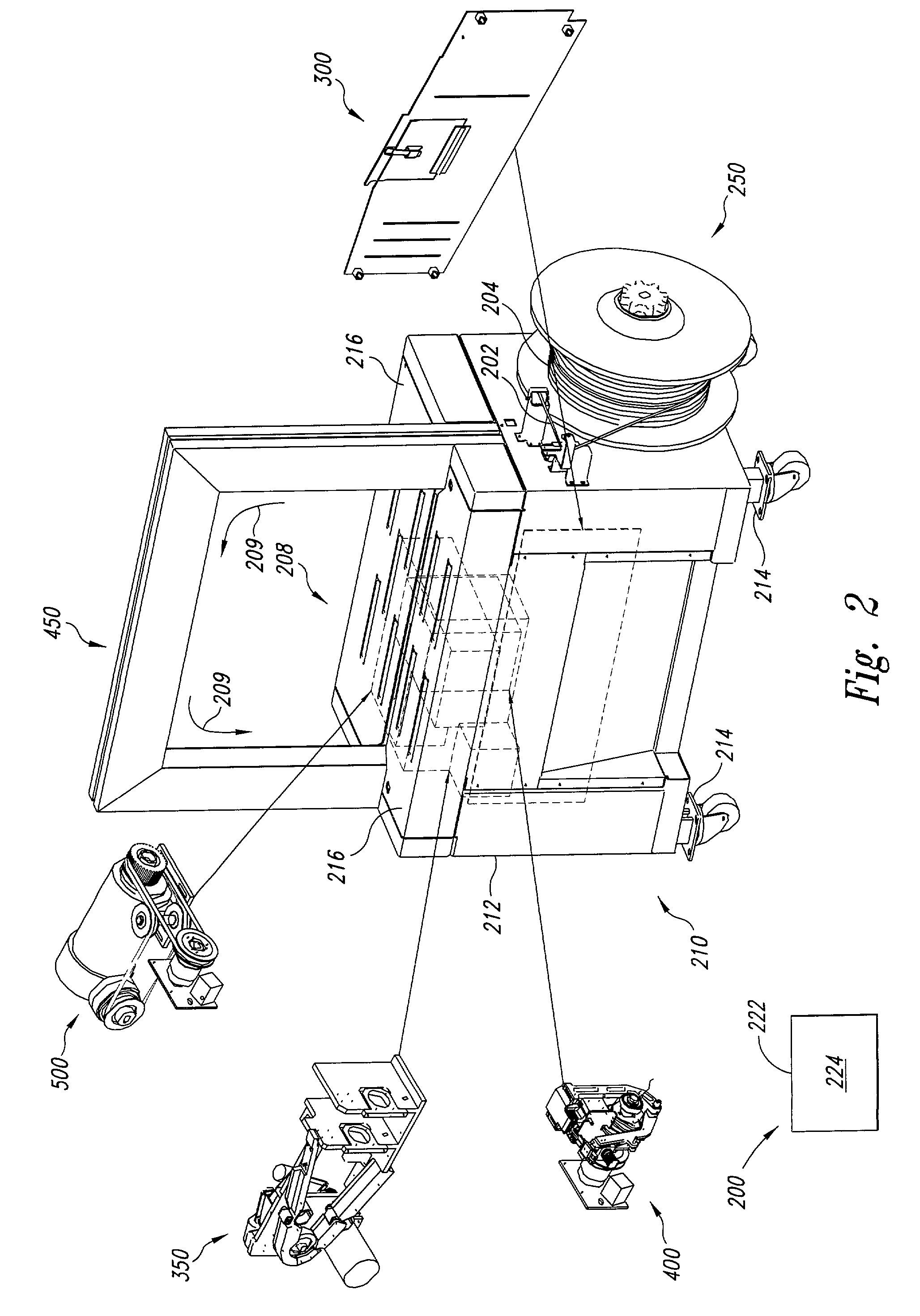
[0046] FIG. 2 is an isometric view of a strapping machine 200 in accordance with an embodiment of the invention. The strapping machine 200 includes seven major subassemblies: a frame 210, a control system 220, a dispenser 250, an accumulator 300, a feed and tension unit 350, a sealing head 400, a drive assembly 500, and a track 450. The subassemblies are of modular construction, which allows them to be used in multiple frame configurations.

[0047] Throughout the following discu...


PUM


Abstract

Apparatus and methods for applying flexible straps around objects include a feed and tension unit a feed drive wheel and a feed pinch wheel, a primary tension drive wheel and a primary tension pinch wheel, and a secondary tension drive wheel and a secondary tension pinch wheel, wherein at least one of the pinch wheels is controllably biased against the respective drive wheel by a solenoid that is controlled in two stages: a first stage that provides a full feed or tensioning force and a second stage that provides a reduced feed or tensioning force by altering the pulse width modulation of the solenoid. In another embodiment, the three sets of wheels of the feed and tension unit are configured to provide a simplified "V-shaped" strap path that reduces bending of the strap, thereby reducing friction and consequent feeding difficulties. In another embodiment, the feed and tension unit includes inner and outer guides that form a strap channel through the feed and tension unit to provide easy access to the strap path for clearing the strap path in the event of a jam. In another embodiment, a track assembly includes a plurality of sections providing modularity of construction. Each section includes a backplate attached to at least one support member, and a slotted cover pivotably attached to the at least one support member proximate the backplate and moveable between an open position spaced apart from the backplate and a closed position proximate the backplate. In another embodiment, a cutting assembly for severing strap material includes a press platen and a cutter having a first cutting blade along a first edge thereof and a second cutting blade along a second edge thereof, the cutter being removably and variably engaged to the press platen.

Description

TECHNICAL FIELD[0001] This invention relates to apparatus and methods for applying flexible straps around bundles of objects.BACKGROUND OF THE INVENTION[0002] Many high-speed, automatic strapping machines have been developed, such as those disclosed in U.S. Pat. Nos. 3,735,555; 3,884,139; 4,120,239; 4,312,266; 4,196,663; 4,201,127; 3,447,448; 4,387,631; 4,473,005; 4,724,659, 5,379,576, 5,414,980, 5,613,432, and 5,809,873. As disclosed by the devices in these patents, a conveyor belt typically conveys a bundle at high speed to a strapping station where straps are automatically applied before the conveyor belt moves the strapped bundle away from the device.[0003] Typical strapping machines employ an initial or primary tensioning apparatus that provides an initial tensioning of the strap about the bundle. A secondary tensioning apparatus thereafter provides increased or enhanced tension of the strap. A sealing head then seals the strap, typically through the use of a heated knife mecha...

Claims


Application Information

Patent Timeline
Patent Type & Authority Applications(United States)
IPC IPC(8): B65B13/22B65B13/32
CPCB65B13/22B65B2210/12B65B13/18B65B59/003B65B59/005B65B13/00
Inventor HELLAND, GARYBALLOU, RICHGREENLUND, MARLASMITH, DON
Owner SAMUEL MANU TECH
Why Eureka
Try Eureka