Method and device for transmitting signals from a position measuring arrangement to an evaluation unit

a position measuring arrangement and signal technology, applied in the direction of instruments, electrographic process equipment, electrography/magnetography, etc., can solve the problems of signal interruption and arrangement must be immediately stopped

Inactive Publication Date: 2010-12-07
DR JOHANNES HEIDENHAIN GMBH +1
View PDF4 Cites 1 Cited by
  • Summary
  • Abstract
  • Description
  • Claims
  • Application Information

AI Technical Summary

Benefits of technology

[0015]The attainments in accordance with the present invention do not require any additional signal transmission lines for transmitting a warning signal from the position measuring arrangement to the evaluation unit and therefore meet the requirement for keeping the outlay for required signal connections as low as possible and for assuring compatibility with the customary number of signal transmission lines. Moreover, the method in accordance with the present invention and the device in accordance with the present invention assure that the incremental position signals can continue to be transmitted in the warning state, so that the machine equipped with the position measuring arrangement need not be stopped immediately in case of the occurrence of a warning state.

Problems solved by technology

The disadvantage of this type of transmission of a warning signal is the requirement for a separate warning signal transmission line, which goes counter to the demand to keep the number of required signal transmission lines between the position measuring arrangement and the downstream-arranged evaluation unit as low as possible.
A substantial disadvantage of this type of transmission of a warning signal lies in that the transmission of signals is interrupted in the warning state, and the machine equipped with the position measuring arrangement must be immediately stopped.

Method used


Image

  • Method and device for transmitting signals from a position measuring arrangement to an evaluation unit
  • Method and device for transmitting signals from a position measuring arrangement to an evaluation unit
  • Method and device for transmitting signals from a position measuring arrangement to an evaluation unit

Examples


Embodiment Construction

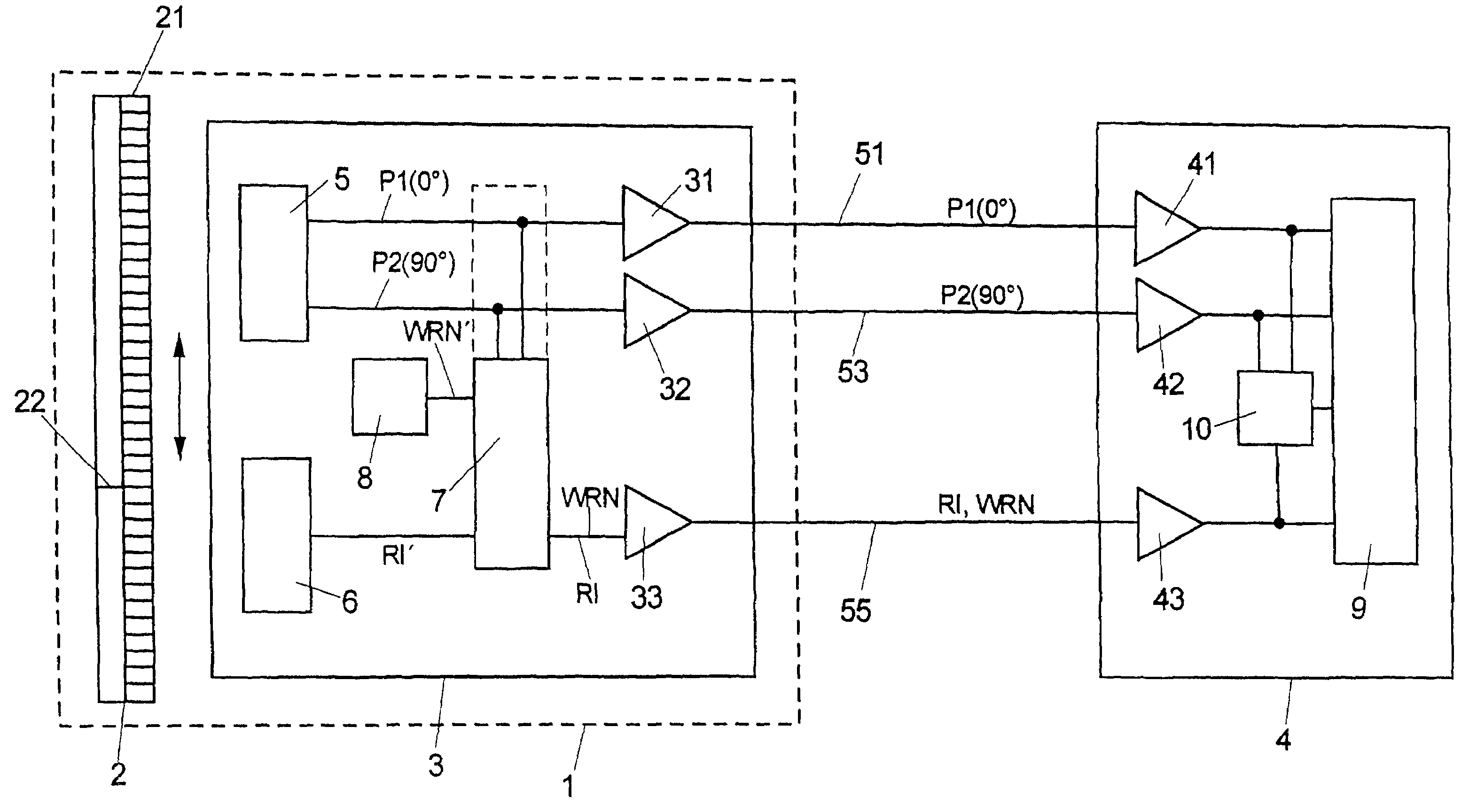
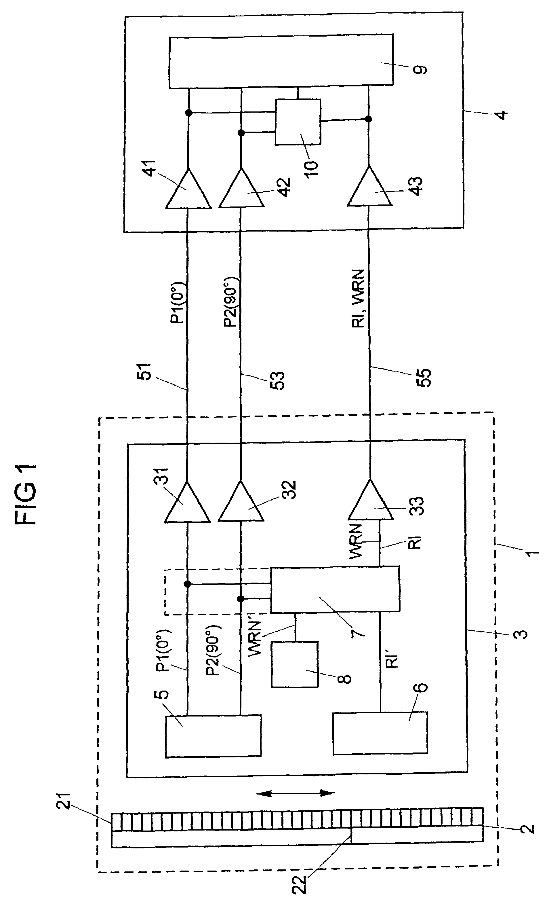
[0038]FIG. 1 shows a block wiring diagram of a position measuring system, having a position measuring arrangement 1 including a scale graduation 2 and a scanning unit 3, which can be moved relative to the latter. Position signals P1, P2 and a reference pulse RI, which is logically interconnected to the position signals P1, P2, are generated by the position measuring arrangement 1 and are transmitted via signal transmission lines 51, 53, 55 to an evaluation unit 4. For example, the scale graduation 2 and the scanning unit 3 are connected with parts of a machine tool which are movable in relation to each other and whose relative position to each other is to be determined, while the evaluation unit 4 includes a numerical machine tool control, for example, or is integrated in it.

[0039]Alternatively to the exemplary embodiment represented in FIG. 1 of a linear movement of the parts which are movable in relation to each other, the attainment of one of the objects in accordance with the pr...


PUM


Abstract

A method for transmitting signals from a position measuring arrangement to an evaluation unit, the method including transmitting position signals, reference pulses, and warning signals indicating a malfunction state from a position measuring arrangement for determining the position of two elements of a machine which are movable relative to each other, to an evaluation unit. The method further includes logically interconnecting the reference pulses with the position signals in such a way that, in a malfunction-free state, a valid status combination for outputting the reference pulses and an invalid status combination for outputting the reference pulses appear in each period. The method including transmitting warning signals indicating a malfunction state during the invalid status combination of the position signals and the reference pulses which, in the malfunction-free state, is invalid for outputting the reference pulses.

Description

RELATED APPLICATIONS[0001]Applicants claim, under 35 U.S.C. §119, the benefit of priority of the filing date of Jul. 12, 2007 of a German patent application, copy attached, Serial Number 10 2007 033 009.1, filed on the aforementioned date, the entire contents of which is incorporated herein by reference.BACKGROUND[0002]1. Technical Field[0003]The present invention relates to a method for transmitting position signals and reference pulses, as well as warning signals indicating a malfunction state, from a position measuring arrangement for determining the position of two elements of a machine which are movable relative to each other, to an evaluation unit. The present invention further relates to a device for transmitting substantially rectangular-shaped position signals and reference pulses, as well as warning signals indicating a malfunction state, from a position measuring arrangement for determining the position of two elements of a machine which are movable relative to each other...

Claims


Application Information

Patent Timeline
Patent Type & Authority Patents(United States)
IPC IPC(8): G08B21/00
CPCG03G15/50
Inventor WAGNER, JOHANNESMAYER, ELMAR
Owner DR JOHANNES HEIDENHAIN GMBH
Why Eureka
Try Eureka