Systems and methods for immobilization

a technology of immobilization and system, applied in the field of systems and methods for reducing mobility, can solve the problems of large number of non-compliance subjects, fewer police officers, and incomplete immobilization of targets, so as to reduce the risk of serious injury or death, and effectively immobilize targets

Active Publication Date: 2007-10-09
AXON ENTERPRISE INC
View PDF6 Cites 58 Cited by
  • Summary
  • Abstract
  • Description
  • Claims
  • Application Information

AI Technical Summary

Benefits of technology

[0015]Circuits and methods according to various aspects of the present invention solve the problems discussed above at least in part by more effectively immobilizing a target, by reducing the risk of serious injury or death, and / or by immobilizing for a period of time with an expenditure of energy less than systems using techniques of the prior art.

Problems solved by technology

The EMD waveform apparently overrides the target's nervous system's muscular control, causing involuntary lockup of the skeletal muscle, and may result in complete immobilization of the target.
Unfortunately, the relatively higher energy EMD waveform is generally produced from a higher power capability energy source.
Further, thousands of police officers are injured as a result of confrontations with non compliant members of the general public each year.
Even larger numbers of these non-compliant subjects are injured in the process of being taken into police custody.
Without systems and methods for delivering more effective stimulus signals, further improvements in cost, reliability, range, and effectiveness cannot be realized for conducted energy weapons.
Applications for conducted energy weapons will remain limited, hampering law enforcement and failing to provide increased self defense to individuals.

Method used


Image

  • Systems and methods for immobilization
  • Systems and methods for immobilization
  • Systems and methods for immobilization

Examples


Embodiment Construction

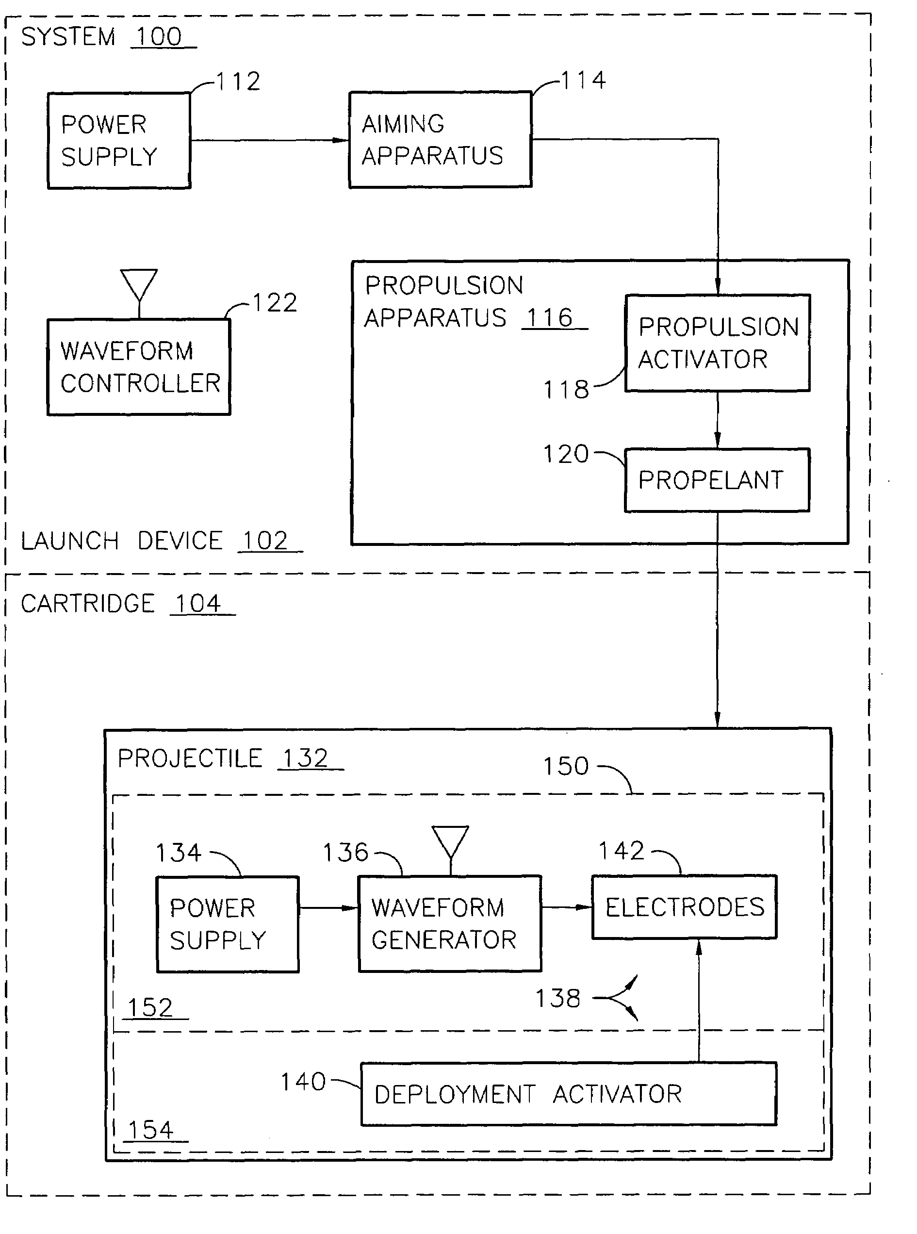
[0021]A system according to various aspects of the present invention delivers a stimulus signal to an animal to immobilize the animal. Immobilization is suitably temporary, for example, to remove the animal from danger or to thwart actions by the animal such as for applying more permanent restraints on mobility. Electrodes may come into contact with the animal by the animal's own action (e.g., motion of the animal toward an electrode), by propelling the electrode toward the animal (e.g., electrodes being part of an electrified projectile), by deployment mechanisms, and / or by gravity. For example, system 100 of FIGS. 1-4 includes launch device 102 and cartridge 104. Cartridge 104 includes one or more projectiles 132, each having a waveform generator 136.

[0022]Launch device 102 includes power supply 112, aiming apparatus 114, propulsion apparatus 116, and waveform controller 122. Propulsion apparatus 116 includes propulsion activator 118 and propellant 120. In an alternate implementat...


PUM


Abstract

Systems and methods for immobilizing a target such as a human or animal with a stimulus signal coupled to the target via electrodes provide the stimulus signal in accordance with a strike stage, a hold stage, and a rest stage. Systems include a launch device and separate projectile, where the projectile includes a battery, a waveform generator, and electrodes. The strike stage and hold stage may include pulses at a pulse repetition rate, for example, from 10 to 20 pulses per second, each pulse delivering a predetermined amount of charge, for example, about 100 microcoulombs at less than about 500 volts peak. The hold stage may continue immobilization at a lesser expenditure of energy compared to the strike stage. Because the strike stage and hold stage may immobilize by interfering with skeletal muscle control by the target's nervous system, a rest stage may allow the target to take a breath.

Description

CROSS-REFERENCE TO RELATED APPLICATIONS[0001]This application is a continuation in part of and claims priority to U.S. application entitled “Systems and Methods Using an Electrified Projectile” by Patrick W. Smith, et al., filed Nov. 13, 2003, incorporated herein by reference; and claims priority under 35 U.S.C. .sctn. 119(e) to now abandoned U.S. application Ser. No. 60 / 509,577 filed on Oct. 7, 2003 by Patrick Smith et al., incorporated herein by reference; and to now abandoned U.S. application Ser. No. 60 / 509,480 filed on Oct. 8, 2003 by Patrick Smith et al., incorporated herein by reference.GOVERNMENT LICENSE RIGHTS[0002]The present invention may have been, in part, derived in connection with U.S. Government sponsored research. Accordingly, the U.S. Government has a paid-up license in this invention and the right in limited circumstances to require the patent owner to license others on reasonable terms as provided for by the terms of contract No. N00014-02-C-0059 awarded by the O...

Claims


Application Information

Patent Timeline
Patent Type & Authority Patents(United States)
IPC IPC(8): A61D3/00F42B12/36H05C1/06
CPCF41H13/0012H05C1/06F42B12/36
Inventor SMITH, PATRICK W.NERHEIM, MAGNE H.
Owner AXON ENTERPRISE INC
Why Eureka
Try Eureka