Tail lamp structure

a technology of tail lamps and tubes, applied in the direction of cycle equipment, lighting and heating apparatus, lighting support devices, etc., can solve the problem of disturbing the design degree of freedom

Inactive Publication Date: 2010-12-14
HONDA MOTOR CO LTD
View PDF9 Cites 7 Cited by
  • Summary
  • Abstract
  • Description
  • Claims
  • Application Information

AI Technical Summary

Benefits of technology

[0008]It is an object of an embodiment of the present invention to eliminate the problems described above by providing a tail lamp structure whose height in an upward and downward direction can be reduced to achieve miniaturization thereof.
[0013]With the tail lamp structure according to an embodiment of the present invention, the board on which the stop lamp LED and the tail lamp LED are mounted in a forwardly and backwardly spaced relationship from each other and are arranged in the forward and backward direction of the vehicle. Thus, the height of the tail lamp structure in the upward and downward direction of the vehicle is reduced, and miniaturization can be anticipated.
[0016]With the tail lamp structure according to an embodiment of the present invention, since tail lamp indication is performed on the upper side of the board while license lamp irradiation can be performed on the lower side of the board, the necessity to provide the license lamp at a different place is eliminated, which makes the tail lamp structure smart in design.

Problems solved by technology

Thus, the degree of freedom is disturbed in terms of the design.

Method used


Image

  • Tail lamp structure
  • Tail lamp structure
  • Tail lamp structure

Examples


first embodiment

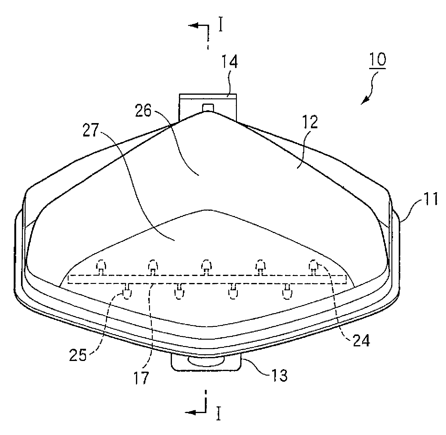
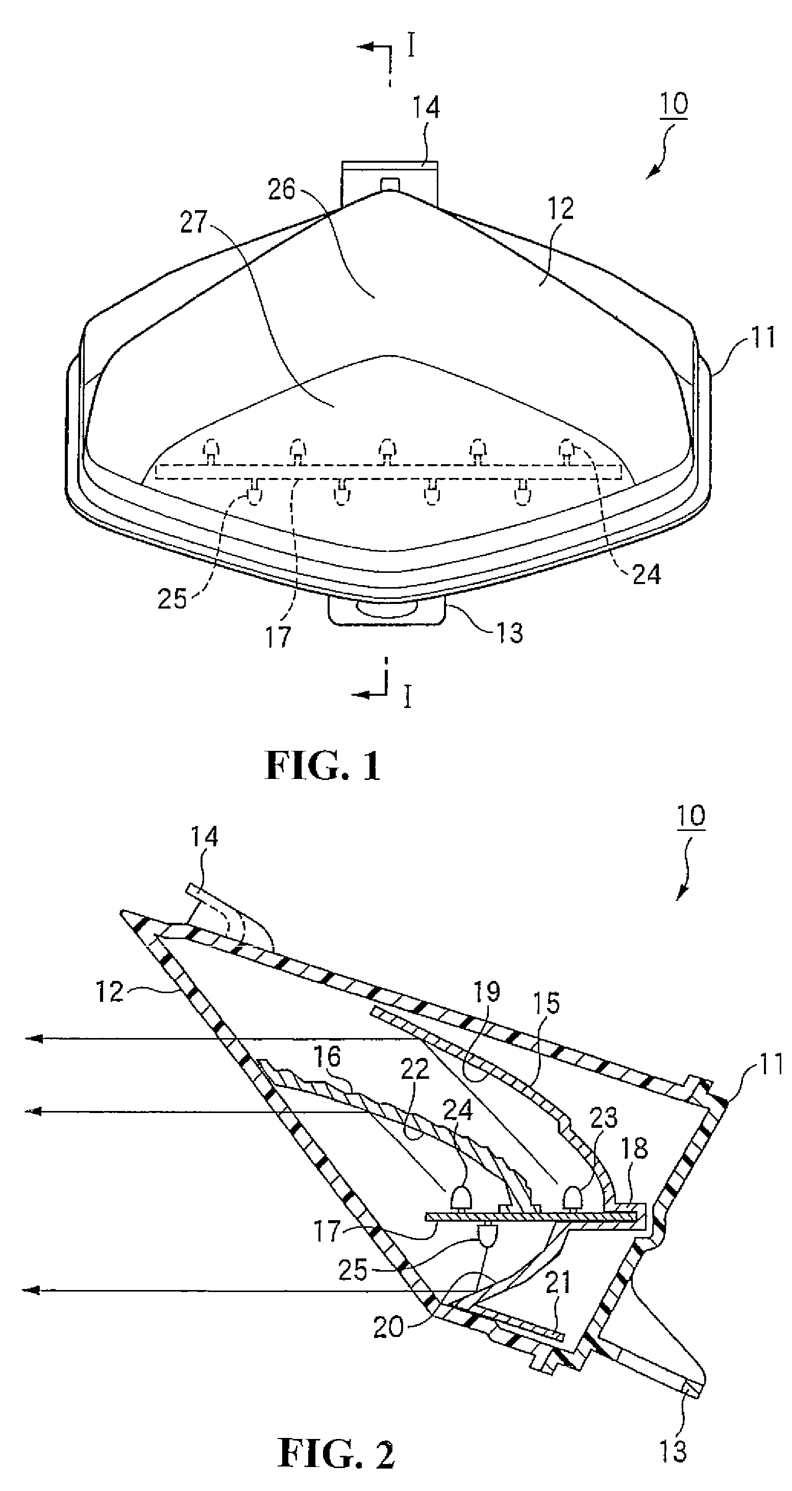
[0023]FIGS. 1 and 2 show the present invention, wherein FIG. 1 is a front elevational view of a tail lamp unit which uses the tail lamp structure according to the present invention and FIG. 2 is a sectional view taken along line I-I of FIG. 1. It is to be noted that the terms front, back, right and left in the description represent directions as viewed from an operator of the motorcycle.

[0024]As shown in FIG. 1, the tail lamp unit 10 which uses the tail lamp structure of the present invention includes a tail lamp case 11 and a tail lamp lens 12.

[0025]The tail lamp case 11 is made of a resin material having a color conforming to the color of the vehicle. A bracket 13 for attachment to the vehicle is formed at a front portion of the tail lamp case 11 such that it projects obliquely forwardly.

[0026]The tail lamp lens 12 is made of a red resin material and is formed in a triangular shape as viewed in a vertical section which tapers rearwardly. A securing portion 14 of a hook shape which...

second embodiment

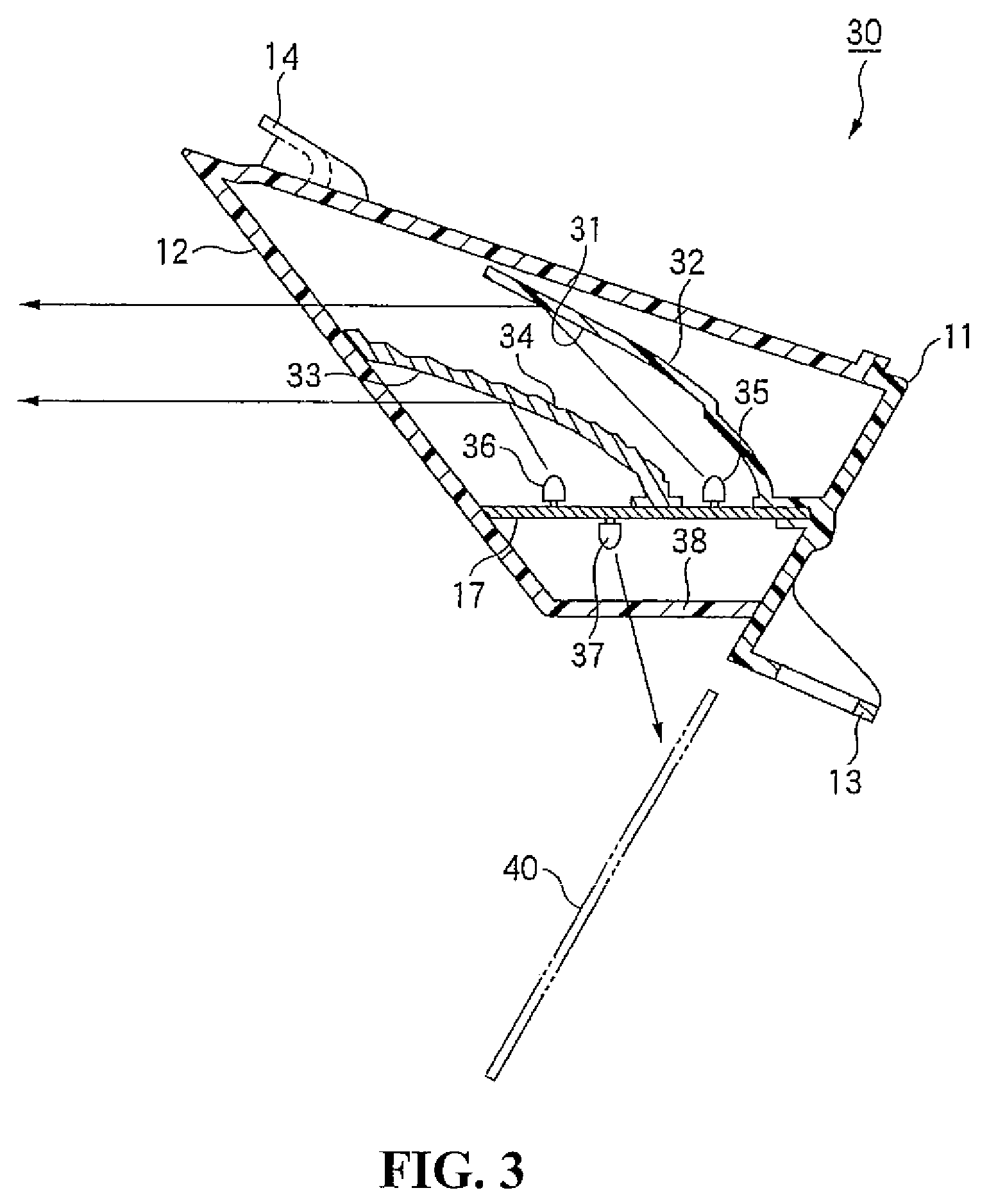
[0037]Now, a second embodiment of the tail lamp structure of the present embodiment is described with reference to FIG. 3. FIG. 3 is a sectional view of a tail lamp unit which uses the tail lamp structure of the present invention corresponding to the section taken along line I-I of FIG. 1. It is to be noted that, in the following description of the second embodiment, a description of the components overlapping with those and components similar in function to those of the first embodiment described above is simplified or omitted by applying like or corresponding reference numerals to the components.

[0038]As shown in FIG. 3, in the tail lamp unit 30 of the second embodiment, a first reflector 32 is provided having a tail lamp reflecting face 31 extending in a curved shape obliquely upwardly and rearwards of the vehicle and a second reflector 34 is arranged rearwardly of the first reflector 32 with a stop lamp reflecting face 33 extending in a curved shape obliquely upwardly and rearwa...


PUM


Abstract

To provide a tail lamp structure wherein a height in an upward and downward direction can be reduced to achieve miniaturization thereof. A tail lamp structure is equipped at a rear portion of a motorcycle. A board on which a stop lamp LED and a tail lamp LED are mounted in a spaced relationship from each other forwardly and backwardly is disposed in the forward and backward direction of the vehicle. The stop lamp LED and said tail lamp LED are isolated from each other by a reflector.

Description

CROSS-REFERENCE TO RELATED APPLICATIONS[0001]The present application claims priority under 35 USC 119 to Japanese Patent Application No. 2007-077552 filed on Mar. 23, 2007 the entire contents of which are hereby incorporated by reference.BACKGROUND OF THE INVENTION[0002]1. Field of the Invention[0003]This invention relates to a tail lamp structure for use with a stop lamp or a tail lamp in a motorcycle.[0004]2. Description of Background Art[0005]A conventional tail lamp structure is known wherein a tail lamp structure includes LEDs that are disposed in a juxtaposed relationship in an upward and downward direction of a vehicle. See, for example, Japanese Patent Laid-Open No. 2003-229005.[0006]However, in the conventional tail lamp structure described above, since the LEDs are disposed in a juxtaposed relationship in an upward and downward direction of the vehicle, an increased height dimension in the upward and downward direction is required.[0007]Further, together with the arrangeme...

Claims


Application Information

Patent Timeline
Patent Type & Authority Patents(United States)
IPC IPC(8): F21S8/10F21W107/17
CPCB60Q1/0058B60Q1/2607B60Q1/2696B62J6/04F21Y2101/02F21Y2115/10F21Y2107/90B62J6/045F21S41/192
Inventor OTA, HIROYASUOHASHI, HAYATOASHIHARA, EIJI
Owner HONDA MOTOR CO LTD
Why Eureka
Try Eureka