Tolerance ring having various end tab designs to prevent interlocking

a technology of tolerance rings and end tabs, applied in the direction of slip couplings, rod connections, instruments, etc., can solve the problems of data loss, tribological failure of the interface, damage to the disk and head,

Active Publication Date: 2010-12-14
INTRL PLEX TECH INC
View PDF73 Cites 38 Cited by
  • Summary
  • Abstract
  • Description
  • Claims
  • Application Information

AI Technical Summary

Benefits of technology

[0014]A tolerance ring having a cylinder with a predetermined length between two ends, and a gap along the predetermined length of the cylinder. The gap has a first and a second edge. Protruding from the first edge of the gap is a first tab that overlaps the second edge. A second tab may protrude from the second edge of the gap to couple with the first tab. The first tab may have a hook-shaped end that couples to a hook-shaped end on the second tab. The first tab may be configured so that it is engageable with an aperture in the second edge of the gap. The tab configuration may have a cavity or aperture to account for mass eccentricity of the tolerance ring as required. The tab may be configured into an alternate L-shaped or U-shaped flange that hooks into the opening of an aperture in the opposite edge of the gap or an aperture in an opposing tab. The tabs may be configured to engage each other. In another embodiment, a non-linear gap is formed from one end of the cylinder to the other end.

Problems solved by technology

Because there is relative motion between the disk surface and the magnetic head due to the disk rotation and head actuation, continuous contact between the head and disk can lead to tribological failure of the interface.
Such tribological failure, known colloquially as a “head crash,” can damage the disk and head, and usually cause data loss.
Separating interlocked tolerance rings is a labor intensive, time consuming effort that is expensive and subjects the tolerance rings to damage.

Method used


Image

  • Tolerance ring having various end tab designs to prevent interlocking
  • Tolerance ring having various end tab designs to prevent interlocking
  • Tolerance ring having various end tab designs to prevent interlocking

Examples


Embodiment Construction

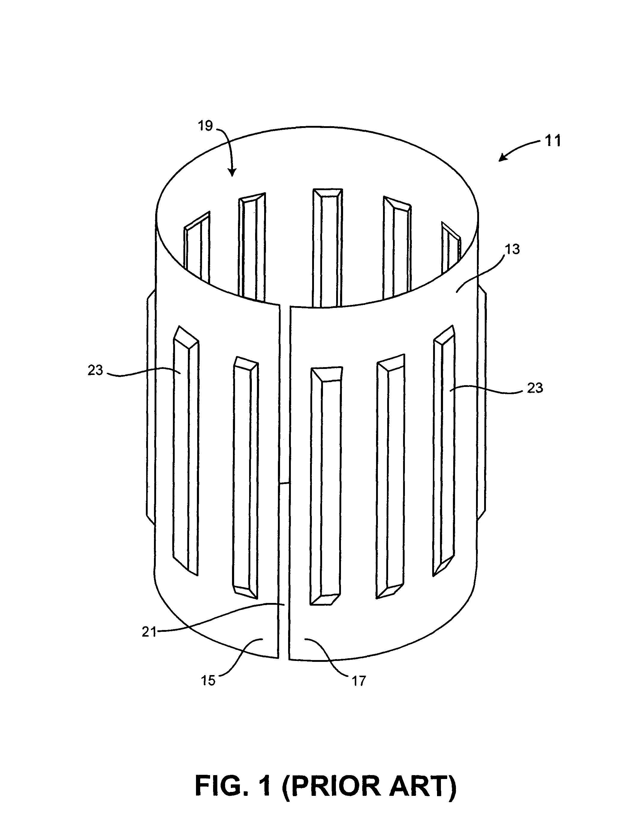
[0030]FIG. 1 illustrates a perspective view of a prior art tolerance ring design 11. In one embodiment, the tolerance ring 11 is made from 300 Series stainless steel. The tolerance ring 11 is formed from a substantially planar base portion that is curved to form a cylinder 13. The cylinder 13 has a first radius about a central axis and extends for a fixed length parallel to the central axis.

[0031]Radial expansion and contraction of cylindrical opening 19 is facilitated by a gap 21 along the length of tolerance ring 11, the gap 21 having a first edge 17 and a second edge 15. This gap 21 allows tolerance rings to readily interlock during shipping and handling because a cylinder 13 of one tolerance ring 11 can enter through the gap 21 and into the cylindrical opening 19 of another tolerance ring 11. Separating interlocked tolerance rings 11 is time consuming, expensive and may subject the tolerance rings 11 to handling damage.

[0032]The tolerance ring 11 has a plurality of contacting po...


PUM

PropertyMeasurementUnit
lengthaaaaaaaaaa
perimeteraaaaaaaaaa
sizeaaaaaaaaaa

Abstract

A tolerance ring configured to prevent interlocking during shipping and handling. The tolerance ring has a cylinder with a first radius about an axis of rotation and a gap in the cylinder surface having a first edge and second edge extending along the axis. The gap in the cylindrical base has a first tab on the first edge and a second tab on the second edge. The first tab is adapted for coupling to the second tab and thereby prevents the interlocking of one tolerance ring with another. The gap can be configured to be non-linear.

Description

BACKGROUND OF THE INVENTION[0001]1. Field of the Invention[0002]This invention relates generally to bearing tolerance rings. More particularly, the invention pertains to tolerance rings used in cartridge bearings for actuator arms in information storage devices, such as hard disk drives.[0003]2. Description of Related Art[0004]A key component of any computer system is a device to store data. One common place for storing massive amounts of data in a computer system is on a disc drive. The most basic parts of a disc drive are a disc that is rotated, an actuator that moves a transducer to various locations on the disc, and electrical circuitry that is used to write and read data to and from the disc. Coupled to the actuator is a head-gimbal assembly (HGA) that includes a head and metal suspension. The HGA's can be stacked together into a head-stack assembly (HSA), which is propelled across the disk surface by the actuator. There are a variety of disc drives in use today, such as hard d...

Claims


Application Information

Patent Timeline
Patent Type & Authority Patents(United States)
IPC IPC(8): F16B7/04G11B21/02
CPCF16C27/00F16D1/0835F16D7/021G11B5/4813F16C41/008Y10T403/7061F16C11/04F16D2001/062F16C2370/12
Inventor HANRAHAN, KEVIN P.SCHMIDT, RYAN J.DEXTER, DAVID D.BRINK, DAMON D.
Owner INTRL PLEX TECH INC
Why Eureka
Try Eureka