Induction and switched reluctance motor

a technology of switching reluctance and motor, which is applied in the direction of motor/generator/converter stopper, dynamo-electric converter control, synchronous motor, etc., to achieve the effect of simplifying logistics and reducing operating costs

Inactive Publication Date: 2010-12-14
BOREALIS TECH LTD
View PDF48 Cites 4 Cited by
  • Summary
  • Abstract
  • Description
  • Claims
  • Application Information

AI Technical Summary

Benefits of technology

[0039]In one embodiment, both of the harmonics used are low order harmonics, for example 1-6. These generate relatively low order pole counts which have a larger pole area than high order pole counts, and are thus more efficient. In one embodiment, one of the harmonic orders used is the first harmonic, the fundamental. In a further embodiment, one of the harmonic orders used is the fundamental and the other is the second or third harmonic. In a further embodiment, blends of Type A harmonic orders are used instead of a single harmonic order, for the reluctance effect.
[0048]Technical advantages of the present invention include: allowing a motor to operate with efficient parameters both at high and at low speeds, opening the market to a new motor type, allowing the motor to be wound with a star connection, reducing operating costs and simplifying logistics.

Problems solved by technology

However, this magnetic field configuration induces substantial rotor currents in the rotor windings, and the interaction produces induction based torque to rotate the rotor.

Method used


Image

  • Induction and switched reluctance motor
  • Induction and switched reluctance motor
  • Induction and switched reluctance motor

Examples


Embodiment Construction

[0055]The present invention combines the benefits of a high phase order induction operation and reluctance-based operation into a single machine.

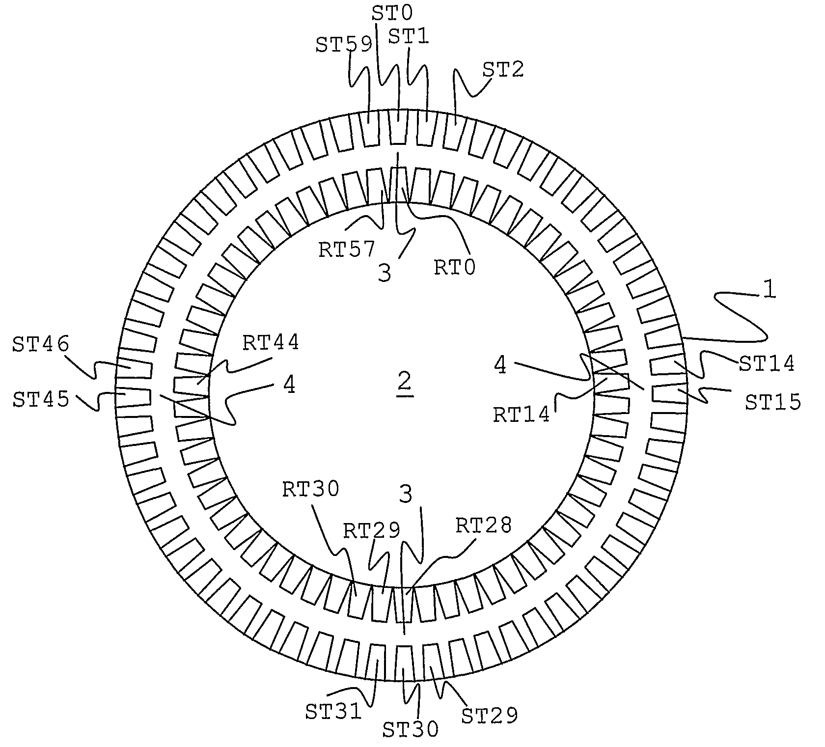
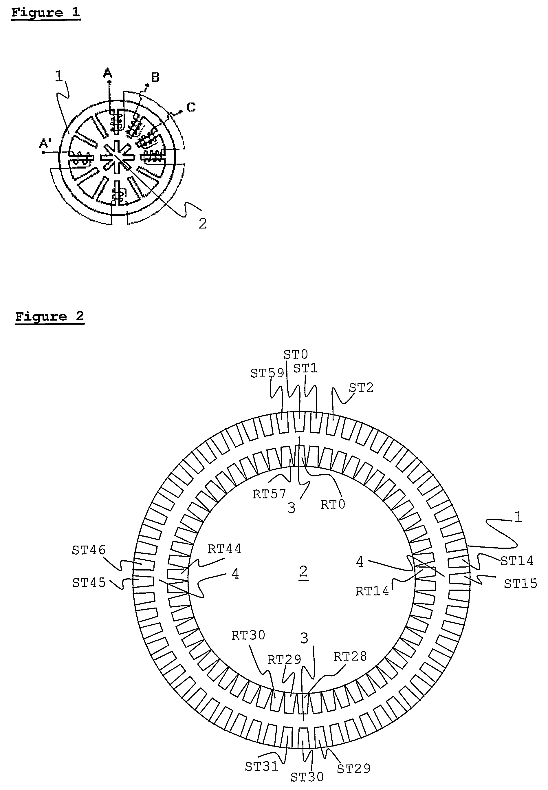
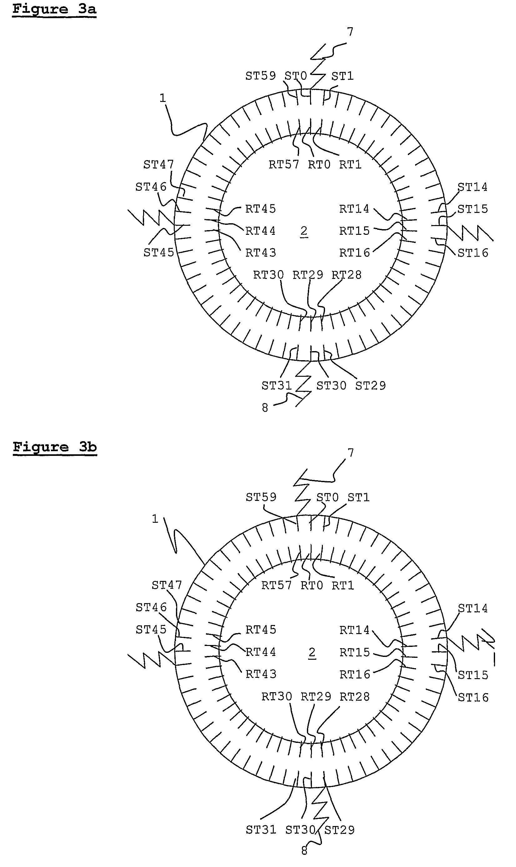
[0056]One embodiment of the present invention is shown in FIG. 2. Stator 1 and rotor 2 each have a high but different number of teeth. The size, dimensions, and spacing of the teeth are intended for purposes of illustration, and are not intended to replicate reality. As may be seen on the diagram Rotor 2 has 58 teeth RT0-RT57, and stator 1 has 60 teeth, ST0-ST59. Only some of the teeth are labeled, for clarity. Both rotor 2 and stator 1 have windings that are standard for induction machines—these are not shown on the diagram, for clarity. There are 60 slots between stator teeth, each containing a different winding phase. The back sides of each winding are wrapped around the outside of the stator, in a toroidal fashion, as described above. Software suitable for both operations, such as, but not limited to, PWM control is used to provide elec...


PUM


Abstract

This application describes a motor designed to operate as a reluctance machine at low speeds and as an induction machine at high speeds. The drive waveform is composed of one or more harmonics to be used to match the reluctance pattern of the stator-rotor, causing the rotor to rotate due to the reluctance effect, and one or more other harmonics to induce current in the rotor, causing the rotor to rotate due to the induction effect and the subsequent interaction of the stator and rotor magnetic fields. The two effects are generally not applied simultaneously.

Description

CROSS-REFERENCE TO RELATED APPLICATIONS[0001]This application is the U.S. national stage application of International Application No. PCT / US2006 / 012483, filed Apr. 5, 2006, which international application was published on Oct. 26, 2006, as International Publication WO / 2006 / 113121 in the English language. The International Application claims the benefit of U.S. Provisional Patent Application No. 60 / 673,021, filed Apr. 19, 2005. This application also claims the benefit of U.S. patent application Ser. No. 11 / 792,967, filed Jun. 13, 2007. U.S. patent application Ser. No. 11 / 792,967 is the U.S. national stage application of International Application No. PCT / US2005 / 045409, filed Dec. 13, 2005, which international application was published on Jun. 22, 2006, as International Publication WO / 2006 / 065988 in the English language. The International Application claims the benefit of U.S. Provisional Patent Application No. 60 / 635,767, filed Dec. 13, 2004, and U.S. Provisional Patent Application No...

Claims


Application Information

Patent Timeline
Patent Type & Authority Patents(United States)
IPC IPC(8): H02P25/00
CPCH02K17/12H02K19/103H02K19/14H02K37/04H02K57/006H02P23/08H02P25/08H02K2213/03H02K2213/09H02K99/20H02P25/092
Inventor EDELSON, JONATHAN SIDNEY
Owner BOREALIS TECH LTD
Why Eureka
Try Eureka